3D printing services

3D printing requests, organized around part definition, build strategy, feature intent, and acceptance.

A 3D printing request should identify the controlling solid model or mesh and revision; file units and scale; intended use and quantity; material, feedstock, colour, property, and environmental requirements; any prescribed additive process family; build coordinate and orientation convention; layer direction or anisotropy boundaries; support, raft, contact, removal, trapped-material, drain, escape, and access constraints where relevant; walls, ribs, bosses, holes, channels, interfaces, fit, threads, and inserts; machining or finish allowances; surface and cosmetic zones; required post-processing; datums, measurement state, inspection method, acceptance criteria, requested records; and timing. These inputs allow process, material, geometry, post-processing, inspection, and fulfillment fit to be reviewed before acceptance.

  • Controlled model, revision, units, and purpose
  • Build, feature, surface, and acceptance requirements
  • Scope confirmed per quote
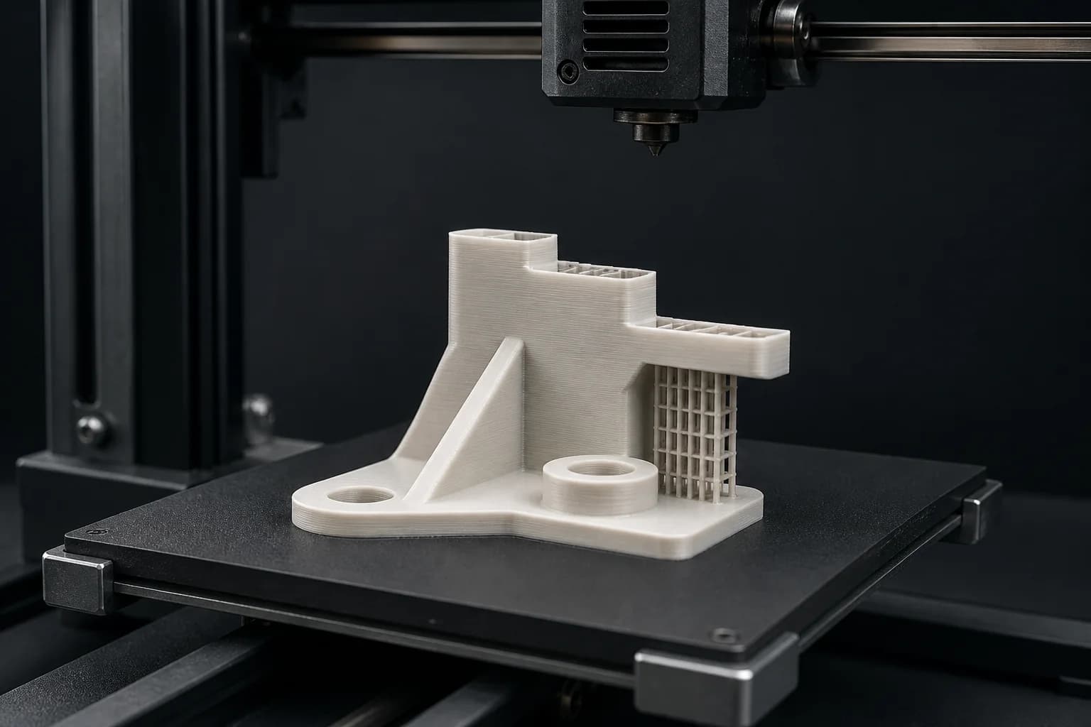
Illustrative additive-build planning scene with a partially formed polymer mounting bracket on a removable build plate, support lattice beneath an overhang, and a parked generic print head
Illustrative additive-build planning reference3D Printing

Capability review

This page describes common request types. Available processes, equipment, tolerances, inspection, documentation, and fulfillment are confirmed for each quote.

Overview

An additive request needs one controlled relationship between digital definition, build strategy, and acceptance.

Additive manufacturing builds physical geometry through successive addition of material from digital part data, but a model alone does not define a purchased part. Solid and tessellated representations can carry different authority, and file units, scale, coordinate system, orientation, mesh condition, repair permission, and allowed geometry changes must be controlled. The interaction of process family, material or feedstock, build direction, layer direction, supports, geometry, and post-processing can influence part properties and measurement; there is no universal wall, feature, support, tolerance, or surface value that applies to every combination. Complex surface topography, internal features and channels, trapped material, anisotropy, residual stress, and post-processing can require specific inspection or test definitions and measurement states. The request should connect intended use and property requirements to critical features, interfaces, support-contact and removal boundaries, final condition, inspection, acceptance, and documentation at one revision. These inputs support project-specific review; they do not establish process or material availability, a printable or production-ready model, achieved strength, density, isotropy, accuracy, surface condition, watertightness, internal cleanliness, finished result, inspection decision, record package, lead time, or fulfillment route before quoting.

Controlled digital definition

Identify the controlling STEP or STP solid model, STL or 3MF mesh when relevant, PDF drawing, revision, units, scale, coordinate system, intended use, quantity, mating assembly or envelope, critical features, file precedence, tessellation and mesh condition, known repair status, and the authority for any repair or geometry change.

Material, build, and support strategy

State the material specification, grade or polymer system, feedstock and property requirements, colour, any prescribed process family, build direction and orientation convention, layer direction or directional-property boundaries, support and raft intent, contact restrictions, removal access, and process-relevant trapped-material, drain, escape, cure, or powder-removal constraints.

Interfaces, final state, and acceptance

Define walls, ribs, bosses, holes, slots, channels and internal features; clearances, fits, threads, inserts and mating interfaces; as-built or post-processed allowances; surface, layer-texture, cosmetic and protected regions; required cleanup and post-processing; datum and support scheme; measurement state; inspection method and coverage; acceptance and rejection criteria; packaging; and requested record fields.

Fulfillment review

Requests are reviewed manually. The fulfillment route and availability are confirmed before acceptance.

Quote inputs

The information that starts a useful 3D printing review.

The quote form accepts private files or a written project description, plus optional process, material, material-source, quantity, and timing details. Select Additive manufacturing in the optional Process field when useful, then use the file or description to define the controlled part data, intended use, material and property requirements, build and support constraints, critical features, final condition, and acceptance.

Controlled files, revision, and part purpose
STEP or STP solid model, STL or 3MF mesh when relevant, PDF drawing, controlling file and revision, units and scale, model coordinate system, quantity, intended use and responsibility, prototype or end-use status as defined by the caller, mating assembly or envelope, critical and cosmetic features, and precedence when the model, mesh, drawing, or notes could conflict; for tessellated data, state tessellation, closed or open mesh condition, known repair status, and whether repair or geometry changes are authorized
Material, feedstock, process, and property boundaries
Material specification, grade or polymer or resin system, reinforcement or fill when relevant, colour, feedstock form and any caller-required lot mapping, supplied-material status, any prescribed additive process family, substitution authority, test-specimen or witness requirements, and required mechanical, physical, thermal, chemical, ultraviolet, flame, electrical or ESD property state and acceptance basis when governed by the design authority
Build orientation, supports, and feature relationships
Part coordinate and build-direction convention, requested orientation and reason when prescribed, layer direction or anisotropy boundaries, support or raft locations, contact and witness limits, removal method and access, protected and cosmetic faces, overhangs, walls, ribs, bosses, holes, slots, channels, cavities, trapped-material risk, drain or escape paths, powder or resin removal and cure access where relevant, mating components, clearances, fits, threads, inserts, and machining or finish allowance
Final state, inspection, records, quantity, and timing
As-built, support-removed, cleaned, cured, heat-treated, machined, coated, assembled or other requested acceptance state as applicable; layer texture and surface-condition requirements; post-processing sequence; datums and support; free or restrained measurement state; critical dimensions and tolerances; inspection or test method, locations and coverage; acceptance and rejection criteria; nonconformance instruction; identification; requested record fields and retention boundary; preservation and packaging; quantity; and target timing
Interactive request review

Explore how build strategy, feature intent, and final-state requirements remain connected.

Select a review point on the fixed additive-part layout to examine build orientation and support-contact boundaries, walls and mating features, and surface, post-processing, and inspection requirements without implying a completed or accepted part.

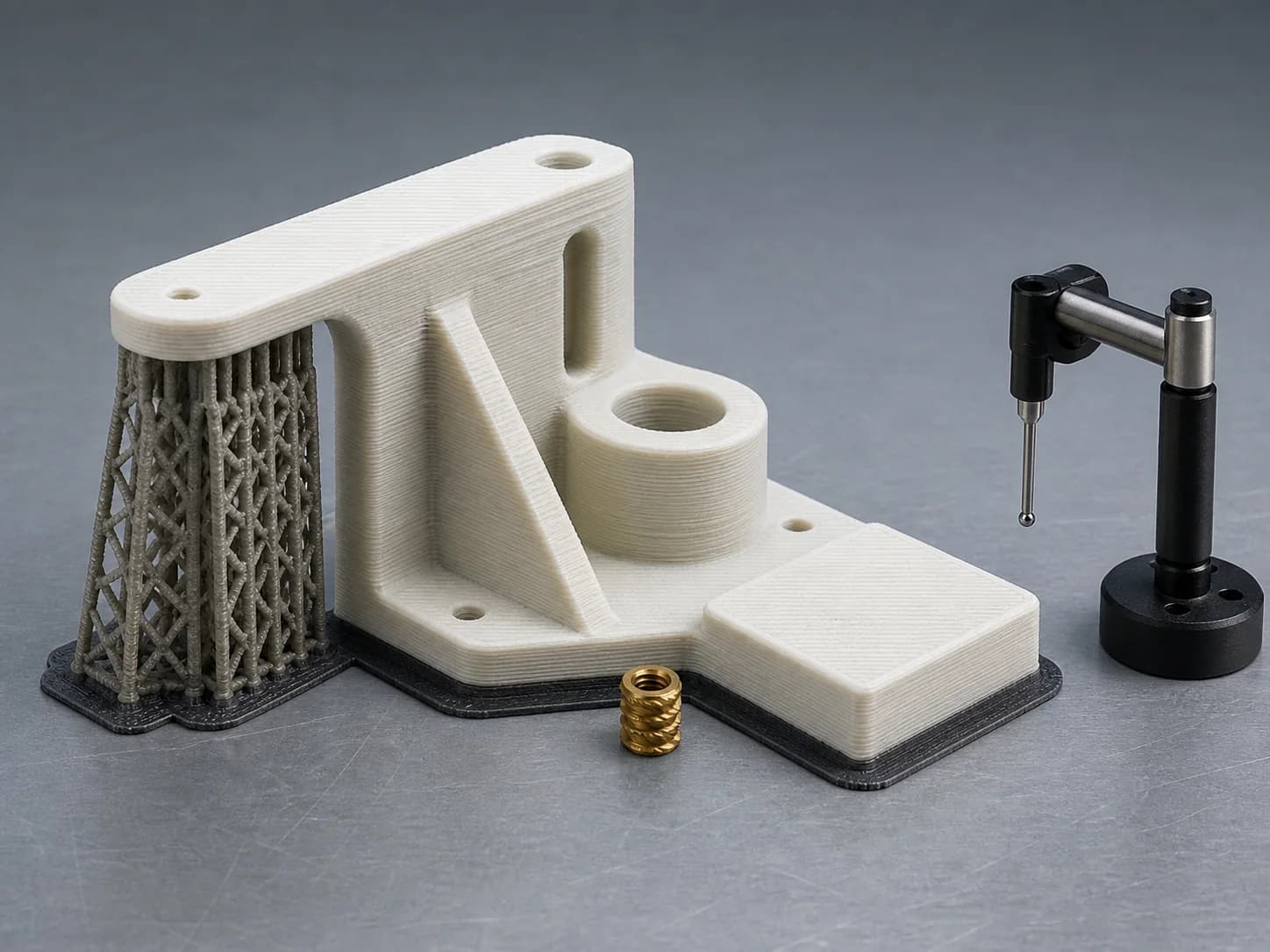
Illustrative additive-part planning layout with a polymer mounting bracket retained on a small build raft, support lattice beneath an overhang, visible layered walls and bosses with a loose brass insert beside an open bore, and a retracted inspection probe beside a flat mating face

One staged bracket, three additive-request zones

Build orientation and support contacts, feature or interface geometry, and surface or inspection boundaries remain visible together while the request details change.

Illustrative planning example only; markers locate request topics. They do not establish a selected process or feedstock, printability, achieved geometry, tolerance, strength, density, surface condition, support-removal result, post-processing result, inspection decision, fulfillment route, or capability.

3D printing request review

What should the additive-part definition explain?

Select a review feature to see the details that help clarify the request.

Build direction, part orientation, and support-contact boundaries

Define the requested build direction and orientation convention, critical or cosmetic faces to protect, support or raft locations, removal access, support-contact limits, and any surfaces that must remain free of contact marks.

  • Controlling part coordinates, requested build direction, orientation convention, and any caller-defined directional-property relationship
  • Raft or support locations, contact surfaces, removal access, trapped-material boundaries, and drain or escape needs where relevant
  • Critical, cosmetic, no-contact, and protected faces plus the allowed support-contact or witness condition for each region

Helpful additive detail

Connect the requested orientation to the controlling coordinate convention, then identify every support or raft region, protected face, contact limit, and removal-access boundary.

Start with your 3D printing files
Model, material, feedstock, process, build, geometry, support, post-processing, inspection and documentation fit; fulfillment route, availability, and timing are confirmed from the submitted information during quote review.

Capabilities

Common 3D printing request patterns, kept easy to scan.

These examples organize caller-defined inputs. File authority, process and material fit, achievable geometry and property state, build and support strategy, post-processing, inspection and record scope, fulfillment, availability, and timing are confirmed from the project files before acceptance.

Form, fit, envelope, concept, and review-model requests

Definition & purpose

Requests organized from the controlled solid model, mesh, drawing and revision; units and scale; intended use and decision point; mating assembly or envelope; critical and cosmetic features; material, colour and property requirements; free or installed condition; quantity; timing; and the acceptance state defined by the caller.

Orientation, support, and process-constrained geometry requests

Build strategy

Requests organized from any prescribed process family, material and feedstock definition, part and build coordinate convention, build direction, layer or property direction, orientation, support or raft locations, contact restrictions, removal access, overhangs, trapped-material risk, drain and escape paths, powder or resin removal, cure access where relevant, and surfaces that remain protected.

Walls, ribs, bosses, holes, channels, threads, and insert requests

Features & interfaces

Requests organized from nominal and minimum-controlled feature geometry, transitions, openings, cavities and internal channels; clearances and fits; mating components and datums; thread definition; insert and hardware identity, installation and access; as-built or post-processed allowance; secondary machining or finishing stock; inspection access; and acceptance criteria.

Surface, post-processing, assembly, inspection, and packaging requests

Final condition

Requests organized from the required acceptance state, support-contact and layer-texture boundaries, visible and cosmetic faces, protected surfaces, cleaning or residue limits, support removal, curing, heat treatment, machining, smoothing, coating or other caller-defined post-processing, insert or hardware installation, assembly interfaces, datum and measurement condition, inspection or test coverage, acceptance and rejection criteria, identification, requested record fields, preservation, and packaging.

Quote workflow

From controlled part data to a confirmed additive-manufacturing review path.

A short, human-managed review keeps intended use, model authority, material and property requirements, build and support constraints, critical features, final state, inspection, acceptance, and open questions visible before work is accepted.

  1. 01

    Share the controlled request

    Upload the controlling solid model or mesh, drawing and revision, units and scale, intended use, material and property requirements, any prescribed process family, build orientation and support constraints, critical features and interfaces, post-processing and final-state requirements, inspection and acceptance criteria, requested records, quantity, and timing.

  2. 02

    Reconcile model, material, build, and support boundaries

    File precedence, solid or tessellated representation, mesh and repair status, units, scale and coordinates, material and feedstock definition, substitution authority, process constraints, build and layer direction, orientation, supports, contacts, removal access, internal-material escape, feature geometry, interfaces, allowances, and design-authority questions are organized for follow-up.

  3. 03

    Resolve final-state and acceptance dependencies

    Process and material fit, achievable feature and property requirements, support and removal strategy, surface and cosmetic boundaries, secondary operations, inserts and assembly, inspection method and measurement state, test and acceptance criteria, requested records, preservation, packaging, fulfillment, timing, and unresolved dependencies are reviewed before acceptance.

  4. 04

    Coordinate the approved baseline

    Once a request is accepted, the controlled files and revision, units and scale, intended use, material and feedstock, prescribed process and property boundaries, build orientation and support plan, critical features and interfaces, allowances, post-processing sequence, final acceptance state, inspection and test criteria, requested records, quantity, timing, and authorized changes become the reference point for project communication.

Request readiness

Small decisions that make 3D printing requests easier to review.

Clear digital definition, intended use, build constraints, feature intent, and acceptance state are more useful than assuming a process, material, orientation, universal design rule, property, or finished result.

Design intent before assumptions
  1. 01

    Keep the model, mesh, drawing, revision, units, and scale aligned.

    Identify the controlling STEP or STP model, STL or 3MF mesh when relevant, drawing and revision, file units and scale, coordinate system, quantity, and precedence rule. State whether the mesh is authoritative or derived and how an updated solid model should propagate to downstream data.

  2. 02

    State mesh condition and repair authority instead of assuming it.

    For tessellated data, identify known open edges, intersections, reversed faces, separate shells, intended cavities, thin regions or prior repairs when relevant. Say whether a closed or manifold mesh is required for the prescribed path and whether repair, remeshing, tessellation changes, scaling, shell merging or geometry deviation may be proposed.

  3. 03

    Connect intended use to material and property requirements.

    State whether the request supports appearance, form, fit, ergonomic, fixture, functional, environmental or other caller-defined evaluation; then identify exact material or polymer system, feedstock and colour, mechanical, thermal, chemical, ultraviolet, flame, electrical or ESD property requirements, property direction and condition, test basis, substitution authority, and who owns design acceptance.

  4. 04

    Map build orientation, supports, contact, and removal access.

    Define the coordinate and orientation convention, build direction and any prescribed orientation, critical and cosmetic faces, layer or directional-property boundaries, support or raft zones, prohibited contacts, witness or contact limits, removal method and tool access, and process-relevant powder, resin, trapped-material, drain, escape or cure-access needs.

  5. 05

    Dimension features, interfaces, and secondary-operation allowance explicitly.

    Identify controlled walls, ribs, bosses, pins, holes, slots, channels, cavities and transitions; mating datums, clearance and fit; threads, inserts and hardware; inaccessible internal features; free or assembled condition; machining, drilling, tapping, smoothing, coating or finishing allowance; protected surfaces; and the sequence connecting the additive state to later operations.

  6. 06

    Tie acceptance to a named part and measurement state.

    State whether each requirement applies as built, support removed, cleaned, cured, heat treated, machined, coated, assembled, free, restrained or otherwise conditioned; then define datums and support, inspection or test method, locations and coverage, critical dimensions and tolerances, surface and cosmetic criteria, acceptance and rejection criteria, nonconformance instruction, requested record fields, preservation, packaging, and handling restrictions.

Materials

Material contexts for 3D printing request review.

These links organize material requirements; they do not establish that an additive process, feedstock, grade, property state, or quantity is available. Exact material identity, process pairing, feedstock and supplied-material status, directional and environmental property requirements, build and support constraints, post-processing, inspection, acceptance, and substitution rules are confirmed for each project.

Material guide

Plastic

Polymer prototype, form, fit, fixture, housing, bracket, duct, cover and interface requests where the exact thermoplastic, photopolymer or other polymer system, grade, reinforcement or fill, colour, feedstock, required property state, build and layer direction, supports, wall and feature intent, trapped-material or drain constraints, surface and post-processing, inspection, and acceptance need review.

Thermoplastic · photopolymer · filled-polymer contexts

View material
Material guide

Aluminum

Lightweight bracket, housing, manifold, fixture, heat-transfer, mount and interface requests where alloy and temper, feedstock definition, supplied-material status, property direction and condition, support and removal strategy, walls and internal channels, machining allowance, heat treatment, surface, inspection, test, requested records, and acceptance state need review.

Alloy · temper · feedstock · post-process context

View material
Material guide

Stainless steel

Bracket, housing, tooling, manifold, fixture and interface requests where exact grade and condition, feedstock requirements, directional properties, supports and removal, trapped-material escape, heat treatment, machining, surface and protected regions, inspection or test method, acceptance, identification, and requested record boundaries need review.

Grade · condition · feedstock · surface context

View material
Material guide

Cobalt

Cobalt-alloy component and tooling requests where the exact alloy system, feedstock and supplied-material status, directional mechanical and thermal property requirements, build and support constraints, heat-treatment and machining sequence, surface and protected features, inspection or test method, acceptance criteria, identification, and requested record fields need review.

Alloy system · feedstock · property · finish context

View material

FAQ

3D printing quote questions.

Start with a private STEP or STP solid model, STL or 3MF mesh when relevant, PDF drawing, or written project description. Add the controlling revision, units and scale, intended use, quantity, material and property requirements, any prescribed process family, build-orientation and support constraints, critical features and interfaces, final condition, post-processing, inspection and acceptance criteria, requested records, and timing. Select Additive manufacturing in the optional Process field when useful.

Identify which file and revision governs geometry, units, scale and coordinates; whether a mesh is authoritative or derived; its known tessellation, shell, closure and repair status; whether repair or geometry changes are authorized; and how drawing dimensions, tolerances, surface notes and acceptance requirements take precedence. Do not assume every mesh needs the same repair rule or that an exported mesh supersedes the solid model.

Name the exact material or polymer system, grade, feedstock and colour, required property state and direction, environmental boundaries, any prescribed process family, substitution authority, coordinate and orientation convention, build and layer direction, supports or raft, prohibited contact regions, removal method and access, cosmetic and critical faces, and process-relevant trapped-material, drain, escape, powder, resin or cure constraints. Process and material fit are confirmed from the complete request.

Dimension controlled walls, ribs, bosses, pins, holes, slots, channels, cavities and transitions; identify inaccessible or trapped-material regions; define mating datums, clearance, fit and assembled condition; specify thread form and inspection intent; provide insert and hardware identity, installation direction and access; and state any as-built, support-removed, machined, coated or other allowance and secondary-operation sequence.

Inspection and documentation requirements can be reviewed during quoting. No certification or report package is implied until confirmed.

Requests are reviewed manually. The fulfillment route and availability are confirmed before acceptance.

Start with the files you have

Ready to review your 3D printing request?

Share the controlled solid model or mesh, drawing and revision, units and scale, intended use, material and property requirements, build-orientation and support constraints, critical features and interfaces, final acceptance state, post-processing, inspection and acceptance criteria, preservation and packaging notes, requested records, quantity, and timing. Pearson will follow up on the details that still need confirmation.

Request a 3D printing quote