Injection molding services

Injection molding requests, organized around part definition, resin, tooling interfaces, and acceptance.

An injection molding request should identify the controlling part model, drawing and revision; units; intended use, quantity and program stage; exact resin designation, supplier and grade, colour, additives, reinforcement, regrind or recycled-content rules, conditioning and required properties; shrinkage basis; parting direction and line; core and cavity side; draft, undercuts and side actions; nominal walls, transitions, ribs, bosses and radii; gate, runner, flow, vent, cooling and ejection boundaries when prescribed; weld-line, flow-line, vestige, flash, sink, warp and cosmetic limits; inserts, overmold substrate and interface requirements; datums, tolerances and measurement state; new or existing tool scope, ownership, cavities, machine interface, trial, approval and change boundaries; secondary operations; inspection and acceptance criteria; requested records; packaging; and timing. These inputs allow resin, part, tooling, process, inspection, and fulfillment fit to be reviewed before acceptance.

  • Controlled part, resin, quantity, and use
  • Parting, features, tooling, and acceptance
  • Scope confirmed per quote
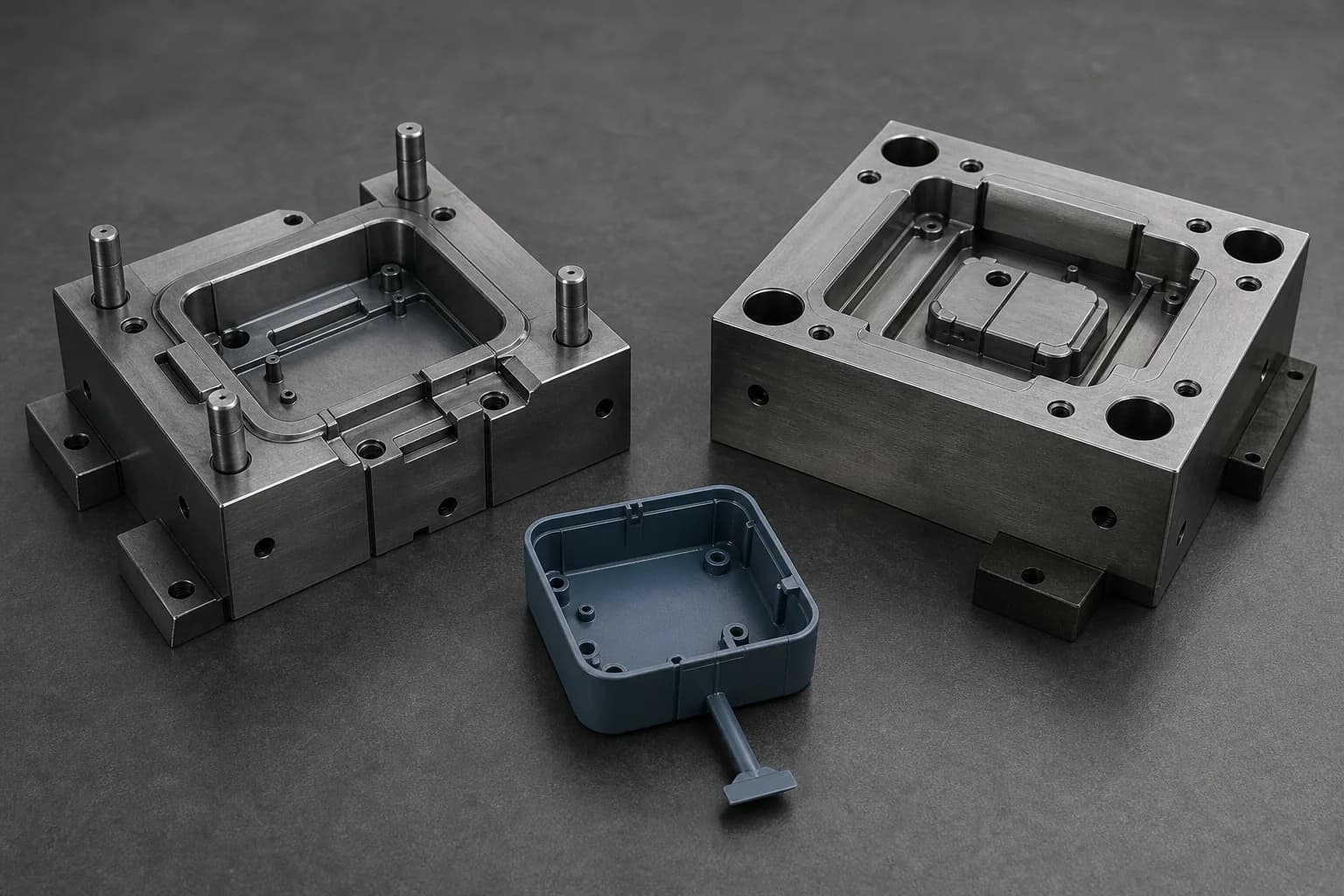
Illustrative injection-mold planning layout with separated generic steel core and cavity inserts beside one blue-gray polymer enclosure shell retained on a short runner and edge-gate tab
Illustrative injection-mold tooling and part-planning referenceInjection Molding

Capability review

This page describes common request types. Available processes, equipment, tolerances, inspection, documentation, and fulfillment are confirmed for each quote.

Overview

A molded part needs one controlled relationship between part data, resin, tool definition, and acceptance.

Injection molding converts a defined resin through a mold into a part, but neither a nominal CAD shape nor a resin-family name alone defines the purchased result. Shrinkage measured from a standard specimen cannot predict an absolute value for every part: exact grade, reinforcement, moisture and conditioning, flow direction and path, wall transitions, gate location, packing and cooling conditions, tool temperature, post-mold history, and measurement state can influence the part. Parting direction and line, draft, undercuts and actions, walls, ribs, bosses, radii, gates, runners, vents, cooling, ejection, inserts, overmold interfaces and secondary operations must be reconciled as one part-and-tool definition. Dimensional and geometrical tolerance rules do not by themselves define surface imperfections such as sink, undesired flow structures, roughness or joint lines; flash, gate vestige, splay, burn, void, short-shot, colour, texture, gloss and other cosmetic or molding conditions also need caller-defined locations, limits and acceptance methods. Tool ownership, existing-tool condition, cavities, interchangeability, machine interface, trials, sample states, approval authority and change rules are separate commercial and technical boundaries. These inputs support project-specific review; they do not establish resin or process availability, moldability, a released tool, achieved fill, shrinkage, dimensions, properties, surface or cosmetic condition, insert or overmold result, approved sample, production quantity, inspection decision, record package, lead time, or fulfillment route before quoting.

Controlled part, program, and resin definition

Identify the governing STEP or STP model, PDF drawing and revision, units, intended use, quantity and program stage, mating assembly, critical and cosmetic features, exact resin supplier and grade, colour and additive package, reinforcement, regrind or recycled-content rule, required properties and condition, shrinkage-data source, substitution authority, supplied-material status, and file precedence.

Parting, molded geometry, flow, and release

Define parting direction and line, core and cavity side, draft convention, undercuts, shutoffs, slides, lifters or other side actions when prescribed, wall and transition intent, ribs, bosses and radii, gate and runner location, flow and weld-line concerns, vents and cooling boundaries, ejection direction and contacts, gate and ejector witness limits, flash and trimming boundaries, and required free or conditioned state.

Tooling, interfaces, final condition, and acceptance

State whether tooling is new, transferred, customer-owned, modified or repair scope; tool and insert materials where controlled; mold base and machine-interface data; cavity and family-tool definition; inserts and overmold substrates; placement, retention and adhesion intent; texture, colour, gloss and cosmetic zones; trial and approval stages; secondary operations; datums, tolerances and inspection state; acceptance and rejection criteria; requested records; ownership, maintenance, storage and change boundaries; preservation and packaging.

Fulfillment review

Requests are reviewed manually. The fulfillment route and availability are confirmed before acceptance.

Quote inputs

The information that starts a useful injection molding review.

The quote form accepts private files or a written project description, plus optional process, material, material-source, quantity, and timing details. Select Injection molding in the optional Process field when useful, then use the file or description to define the controlled part, resin, quantity, molded geometry, tooling and trial scope, final condition, and acceptance.

Controlled files, intended use, quantity, and program
STEP or STP part and assembly models, matching PDF drawing, controlling revision and units, intended use and design authority, quantity and demand or program-stage context, mating components and envelope, critical-to-quality and cosmetic features, free or installed condition, current prototype, bridge, production or replacement-tool definition when caller-governed, existing sample or prior-part status, and precedence when model, drawing, specification, resin data or tool data could conflict
Resin, colour, additives, properties, and shrinkage basis
Exact polymer or resin family, supplier and grade designation, virgin, regrind or recycled-content rule, reinforcement and filler, colour and masterbatch, additives, flame, ultraviolet, ESD, wear, chemical, thermal, mechanical and other design-authority property requirements, lot or batch mapping when required, moisture and preconditioned or as-molded state, test basis, shrinkage data and flow/transverse convention, authorized substitutions, customer-supplied material status, and any witness or specimen requirements
Parting, molded geometry, flow, release, and interfaces
Parting direction and line; core and cavity side; draft definition; undercuts, shutoffs and side actions; nominal walls and transitions; ribs, bosses, gussets, radii, holes, slots, snaps and other features; gate type, location and vestige boundary; runner, flow path, weld-line, vent and cooling constraints when prescribed; ejection direction, contacts and witness limits; flash, trimming and de-gating; inserts, overmold substrates, placement, retention, adhesion, masking and interface requirements; and machining or other secondary-operation allowance
Tooling, trials, final state, inspection, records, and timing
New, transferred, customer-owned, modified or repair-tool scope; existing tool number, condition and available data; tool and insert material requirements; mold base, cavity count, interchangeability and machine-interface data; expected tool-use and maintenance boundaries; trial and sample stages; approval authority and change rules; as-molded, conditioned, trimmed, de-gated, machined, decorated, assembled or other acceptance state; datums, support and free or restrained measurement condition; tolerances; surface and cosmetic criteria; inspection or test method, locations, coverage and sampling; acceptance and rejection criteria; nonconformance instruction; identification; requested record fields and retention; preservation, packaging, quantity and target timing
Interactive request review

Explore how release strategy, molded geometry, and acceptance remain connected.

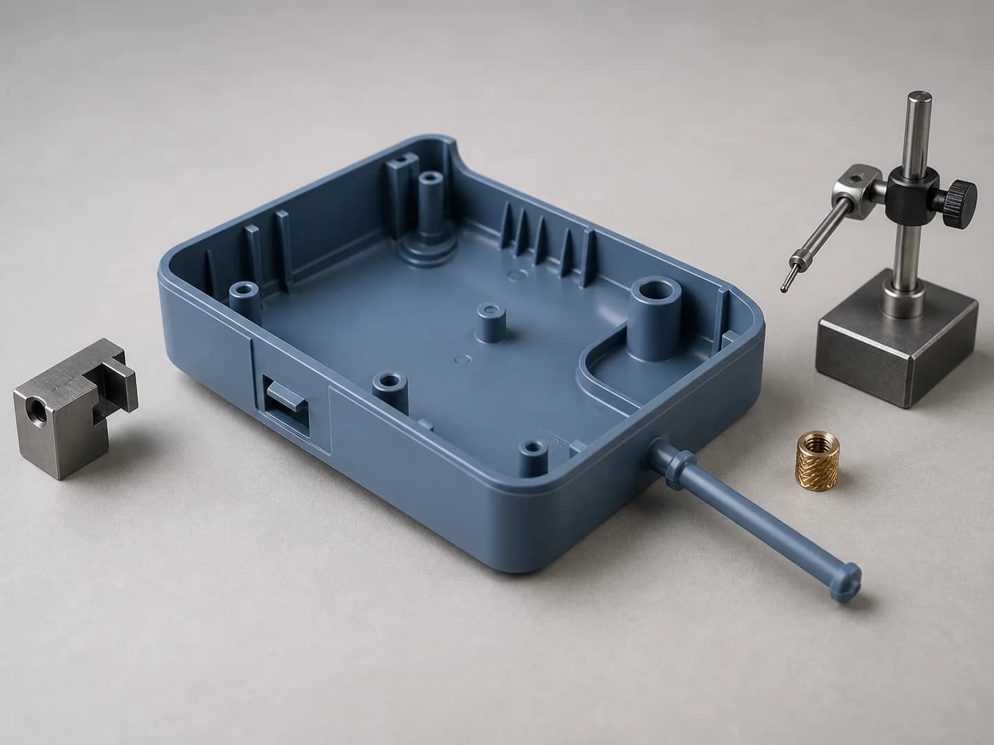
Select a review point on the fixed enclosure layout to examine parting, draft and release boundaries, walls, ribs, bosses and gate relationships, and insert, cosmetic-surface and inspection requirements without implying an approved tool or accepted molded part.

Illustrative injection-molding request layout with one blue-gray polymer enclosure shell retained on a short runner and edge-gate tab, showing a tapered parting edge and side feature, interior walls, ribs and bosses, a loose brass insert, and a retracted probe beside an exterior surface

One staged enclosure, three molding-request zones

Parting and release boundaries, wall and gate relationships, and insert or inspection requirements remain visible together while the request details change.

Illustrative planning example only; markers locate request topics. They do not establish a selected resin or tooling route, moldability, fill, release, achieved geometry, tolerance, sink, warp, surface or cosmetic condition, insert result, tool approval, inspection decision, production quantity, fulfillment route, or capability.

Injection molding request review

What should the molding definition explain?

Select a review feature to see the details that help clarify the request.

Parting direction, draft, side action, and release boundaries

Define the parting direction and line, draft intent, undercuts, side-action or shutoff boundaries, ejection direction, contact limits, and any permitted witness or flash condition.

  • Parting direction and line, pull or ejection direction, draft intent, and the drawing or model convention that controls each region
  • Undercuts, latches, side-action or shutoff boundaries, travel and access needs, contact limits, and protected surfaces
  • Permitted witness, flash and ejector conditions plus exterior, cosmetic, mating and no-contact boundaries

Helpful molding detail

Map the pull and parting conventions to named faces, then identify draft, every undercut or shutoff, ejection direction, contact limit, and permitted witness condition.

Start with your injection molding files
Part, resin, tooling, geometry, appearance, insert, inspection and documentation fit; fulfillment route, availability, and timing are confirmed from the submitted information during quote review.

Capabilities

Common injection molding request patterns, kept easy to scan.

These examples organize caller-defined inputs. Part and resin definition, tool and machine-interface fit, achievable geometry and property state, molding and secondary-operation path, trial and approval scope, inspection and requested records, fulfillment, availability, and timing are confirmed from the project files before acceptance.

Housings, covers, brackets, closures, and general molded-part requests

Part & resin

Requests organized from the controlled part and assembly model, drawing and revision; intended use and quantity; exact resin supplier and grade; colour, reinforcement, additives, regrind or recycled-content rule; required properties and conditioning state; shrinkage basis; critical and cosmetic features; program stage; tool scope; final acceptance state; and authorized substitutions.

Walls, ribs, bosses, snaps, holes, and mating-interface requests

Molded features

Requests organized from nominal wall and transition requirements, ribs, bosses, gussets, radii, holes, slots, openings, snap or clip features, threads and inserts, mating datums, clearance and fit, free or installed state, parting and draft, undercuts and side actions, gate and ejection witness boundaries, machining allowance, secondary operations, inspection access, and acceptance criteria.

Insert-molded, overmolded, and multi-material interface requests

Insert & overmold

Requests organized from insert or substrate identity, source and incoming condition; placement, orientation, retention and support; resin and substrate compatibility requirements; surface preparation, masking, bond or mechanical-lock intent; shutoffs and flash limits; parting, gate, vent, cooling and ejection constraints; interface dimensions; pull, torque, adhesion or other caller-specified test boundaries; cosmetics; and acceptance state.

New-tool, transferred-tool, change, trial, surface, and inspection requests

Tooling & acceptance

Requests organized from tool ownership and location, existing condition and data, mold base and cavity definition, core and cavity inserts, slides, lifters and wear components, runner and gate strategy, vents, cooling and ejection, tool material and condition, machine interface, expected use and maintenance boundaries, trial and sample stages, approval and change authority, texture and cosmetic requirements, molded-condition limits, secondary operations, inspection, requested records, preservation and packaging.

Quote workflow

From a controlled molded-part definition to a confirmed tooling and molding review path.

A short, human-managed review keeps intended use, resin, geometry, parting and release, tooling, trials, final condition, inspection, acceptance, and open questions visible before work is accepted.

  1. 01

    Share the controlled request

    Upload the controlling part and assembly model, drawing and revision, intended use, quantity and program stage, resin and property requirements, shrinkage basis, parting and draft intent, molded features and interfaces, gate and ejection boundaries, new or existing tooling scope, trials, surface and cosmetic criteria, secondary operations, inspection and acceptance requirements, requested records, packaging, and timing.

  2. 02

    Reconcile part, resin, release, and tooling boundaries

    File precedence, resin identity and condition, shrinkage basis, critical and cosmetic features, parting direction and line, draft, undercuts and actions, walls, ribs, bosses and radii, gate, runner, flow, vent, cooling and ejection constraints, inserts or overmold interfaces, existing-tool data, machine interface, ownership and maintenance boundaries, and design-authority questions are organized for follow-up.

  3. 03

    Resolve molding, trial, final-state, and acceptance dependencies

    Resin and process fit, achievable geometry and property requirements, tool and cavity strategy, release and ejection, gate and witness condition, predicted or permitted molding conditions, trial and sample stages, tool changes, surface and cosmetic limits, secondary operations, inspection method and measurement state, acceptance criteria, requested records, preservation, packaging, fulfillment, timing, and remaining dependencies are reviewed before acceptance.

  4. 04

    Coordinate the approved baseline

    Once a request is accepted, the controlled files and revision, intended use and quantity, resin and condition, shrinkage basis, molded features and interfaces, parting and release definitions, gate, flow, vent, cooling and ejection boundaries, tool scope and ownership, machine interface, trial and approval stages, final condition, inspection and acceptance criteria, requested records, packaging, timing, and authorized changes become the reference point for project communication.

Request readiness

Small decisions that make injection molding requests easier to review.

Clear part, resin, tool, release, surface, and acceptance intent is more useful than assuming a standard shrinkage, draft, wall, gate, tool class, molded result, or approval path.

Design intent before assumptions
  1. 01

    Keep the part model, assembly, drawing, revision, units, and program definition aligned.

    Identify the controlling STEP or STP model, assembly context, PDF drawing and revision, units and scale, intended use, quantity or demand context, prototype, bridge, production, transfer, replacement or repair stage when caller-governed, current part and tool status, critical-to-quality and cosmetic features, and precedence when files or specifications conflict.

  2. 02

    Specify the exact resin, property state, and shrinkage basis.

    Provide the polymer or resin family, supplier and grade, form, reinforcement or filler, colour and masterbatch, additives, virgin, regrind or recycled-content rule, lot mapping, moisture and conditioning state, mechanical, thermal, chemical, ultraviolet, flame, ESD or other caller-owned property requirements, test condition, published or measured shrinkage source, flow and transverse convention, and substitution authority. Do not apply test-plaque shrinkage as an unconditional part value.

  3. 03

    Establish parting, draft, undercut, side-action, and release intent together.

    Define the parting direction and line, core and cavity side, draft convention and controlled exceptions, undercuts, shutoffs, slides, lifters, collapsible cores or other actions when prescribed, action travel and access, ejection direction, contact locations, permissible witness, mismatch or flash, protected faces, and how the free molded part is expected to release without treating the layout as an approved tool.

  4. 04

    Connect walls, transitions, ribs, bosses, radii, and sink or warp limits.

    State nominal and local wall intent, transitions, ribs, gussets, bosses, holes and openings, radii, mass concentrations, mating and fastening loads, free or assembled condition, and caller-defined sink, warp, flatness and appearance limits. Tie any exception to resin, gate and flow direction, tool temperature and cooling assumptions, secondary operations, datum scheme and measurement state.

  5. 05

    Map gates, runners, flow, weld lines, vents, cooling, ejection, and cosmetic zones.

    Identify gate type and location when prescribed, runner and cavity relationships, gate vestige and de-gating condition, anticipated flow path and weld-line-sensitive regions, vent and cooling boundaries, ejector or stripper contacts, witness limits, trimming, texture and polish direction, colour and gloss zones, and caller-defined flash, short-shot, burn, void, splay, flow-line, weld-line and other surface acceptance limits.

  6. 06

    Define tool ownership, trials, changes, final state, and acceptance before release.

    State new or existing tool scope, owner and custodian, tool number and available history, mold base and cavity count, family-tool and interchangeability rules, tool and insert materials, machine-interface data, expected use and maintenance or spare boundaries, trial and sample stages, approval authority, change and repair process, secondary operations, conditioned state, datums and support, inspection or test method and coverage, acceptance and rejection criteria, nonconformance instruction, requested record fields, preservation, packaging and retention or disposition.

Materials

Part-resin and mold-tool material contexts for injection molding review.

These links organize molded-part and tooling material requirements; they do not establish that a resin, additive package, insert, tool material, mold route, or quantity is available. Exact grade and condition, shrinkage and property basis, supplied-material status, tool or part role, compatibility, processing and conditioning boundaries, inspection, acceptance, substitution, and ownership rules are confirmed for each project.

Material guide

Plastic

Thermoplastic, thermoplastic-elastomer, filled-resin, reinforced-resin and other molded-part requests where the exact polymer family, supplier and grade, form, colour and additives, virgin or regrind rule, recycled content, shrinkage basis, flow or directional properties, conditioning, environmental and test requirements, walls and features, surface and cosmetic boundaries, secondary operations, inspection and acceptance need review.

Thermoplastic · elastomer · filled-resin contexts

View material
Material guide

Delrin (Acetal)

Acetal part requests where homopolymer or copolymer identity, exact supplier and grade, colour and additives, reinforcement or fill, shrinkage and flow direction, moisture and conditioning state, wall, rib, boss, snap, bearing or wear-interface geometry, gate and weld-line sensitivity, draft and ejection, surface, inspection, property and acceptance requirements need review.

Acetal homopolymer · copolymer · filled-grade contexts

View material
Material guide

Aluminum

Mold-base, core, cavity, insert, prototype, bridge and change-tool requests where the exact alloy and temper, wrought, cast or plate form, hardness and condition, surface treatment, thermal and wear context, gating, venting, cooling and ejection interfaces, insert interchangeability, expected use, repair and maintenance boundaries, inspection, ownership and storage need review.

Mold base · cavity/core insert · bridge-tool context

View material
Material guide

Tool steel

Core, cavity, slide, lifter, shutoff, gate, wear-insert and longer-use tooling requests where exact grade and product form, hardness and heat-treatment sequence, corrosion and wear context, weld or repair history, surface and polish requirement, dimensional and interchangeability intent, cooling and ejection interfaces, inspection, spare, maintenance, ownership, storage and change boundaries need review.

Core/cavity · slide/lifter · wear-insert context

View material

FAQ

Injection molding quote questions.

Start with a private STEP or STP part and assembly model, PDF drawing, or written project description. Add the controlling revision and units, intended use, quantity and program stage, exact resin and property requirements, shrinkage basis, parting and draft intent, walls and features, gate and ejection boundaries, inserts or overmold interfaces, new or existing tool scope, trial and approval needs, final condition, surface and cosmetic criteria, secondary operations, inspection and acceptance requirements, requested records, packaging, and timing. Select Injection molding in the optional Process field when useful.

Name the polymer or resin family, supplier and exact grade, form, reinforcement or filler, colour and masterbatch, additives, virgin, regrind or recycled-content rule, lot mapping when required, moisture and conditioning state, mechanical, thermal, chemical, ultraviolet, flame, ESD and other design-authority property requirements, test condition, shrinkage-data source and direction, and substitution authority. Standard specimen or family data should not be treated as an unconditional prediction for the actual part.

Identify the parting direction and line, core and cavity side, draft convention and exceptions, every undercut and shutoff, slides, lifters, collapsible cores or other actions when prescribed, action and tool access, ejection direction and contact points, witness or flash limits, protected surfaces, and the intended free molded state. These are request and tool-definition inputs, not proof that a part will release or that a tool design is approved.

Define nominal walls and transitions, ribs, bosses, gussets, radii, holes and openings, mass concentrations, mating loads, gate and runner location when controlled, gate vestige, flow path, weld-line-sensitive regions, vents, cooling and ejection contacts, datum and measurement state, and caller-defined sink, warp, flash, short-shot, burn, void, splay, flow-line, weld-line, texture, colour and gloss limits. Avoid universal wall, draft, shrinkage or defect assumptions detached from the exact resin, part and tool.

Inspection and documentation requirements can be reviewed during quoting. No certification or report package is implied until confirmed.

Requests are reviewed manually. The fulfillment route and availability are confirmed before acceptance.

Start with the files you have

Ready to review your injection molding request?

Share the controlled part and assembly model, drawing and revision, intended use and quantity, resin and property requirements, shrinkage basis, parting and draft intent, molded features and interfaces, gate, flow, vent, cooling and ejection boundaries, tooling and trial scope, final condition, surface and cosmetic criteria, secondary operations, inspection and acceptance requirements, preservation and packaging notes, requested records, and timing. Pearson will follow up on the details that still need confirmation.

Request an injection molding quote