Tooth data before method
The tooth system, tooth count, pressure angle, face width, and helical details when relevant are organized before a method is confirmed.
Gear machining services
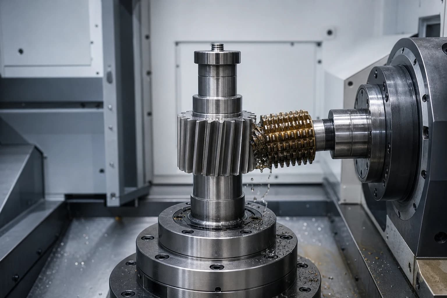
Tooth geometry, the gear blank, bore, hub, keyway or spline, material condition, mating context, heat-treatment sequence, finish, and inspection intent all shape a useful gear review. Share the model and drawing so Pearson can organize those requirements and confirm a project path before acceptance.
Capability review
This page describes common request types. Available processes, equipment, tolerances, inspection, documentation, and fulfillment are confirmed for each quote.
Overview
A gear model can look complete while leaving out information that controls mesh and mounting. Tooth count, module or diametral pitch, pressure angle, face width, helix direction or angle when relevant, bore and hub datums, keyway or spline definition, mating-gear context, material condition, sequence, and inspection intent should be visible before a process path is selected.
The tooth system, tooth count, pressure angle, face width, and helical details when relevant are organized before a method is confirmed.
Bore, hub, faces, shoulders, keyways, splines, and mating-shaft relationships help define how the gear locates and transfers torque.
Material condition, heat-treatment and finish sequence, functional relationships, and documentation expectations belong in the request instead of being inferred.
Fulfillment review
Requests are reviewed manually. The fulfillment route and availability are confirmed before acceptance.
Quote inputs
You do not need every answer before submitting. Share what is known and mark the rest for follow-up.
Interactive gear review
Select a feature on the sample gear to see what the model and drawing should communicate before the project path is confirmed.
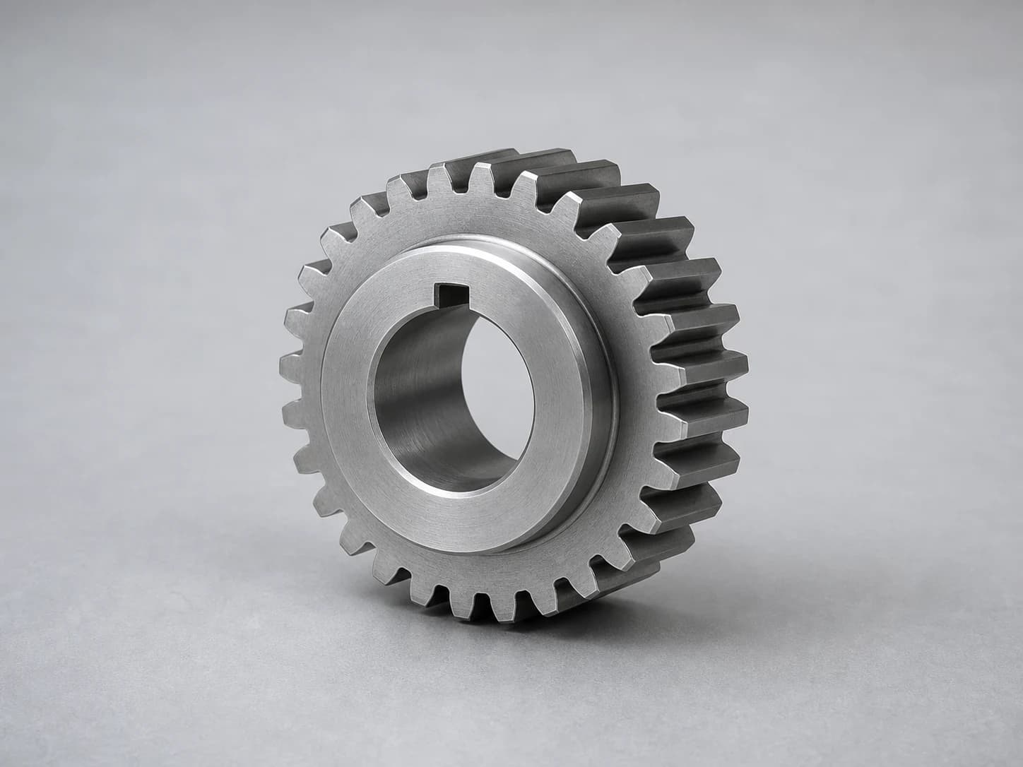
Sample gear feature map
The numbered markers match the review features and guidance panel.
Illustrative example only; markers identify review areas, not dimensions or tolerances.
Gear feature review
Choose a feature group to see the details that help clarify the request.
The tooth definition should identify the system, size, count, face width, and mating context that control how the gear is expected to mesh.
Helpful drawing detail
Include the complete tooth data on the drawing and add mating-gear information when mesh requirements cannot be understood from this part alone.
Process fit, equipment fit, achievable tolerances, inspection, documentation, fulfillment, and timing are confirmed from the project information during quote review.
Capabilities
These examples help identify the likely starting point. Process fit, equipment fit, achievable tolerances, and availability are confirmed from the project files.
Spur and helical gear requests reviewed from their tooth system, tooth count, pressure angle, face width, helical details, mating context, and functional intent.
Gear-body geometry reviewed with blank condition, bore and hub definition, locating faces, shoulders, datum relationships, and the sequence relative to tooth-form work.
Torque-transfer features reviewed with their full geometry, standard or fit information when applicable, orientation, length, access, and mating-shaft context.
Grade and current condition, heat-treatment and finish sequence, critical tooth and mounting relationships, edge condition, documentation, and inspection expectations reviewed together.
Quote workflow
A short, human-managed review keeps tooth data, mounting geometry, sequence, and open questions visible before work is accepted.
Upload the model, drawing, gear data, photos, quantity, material grade or preference, and known mating or functional requirements.
Tooth definition, blank condition, bore and hub datums, torque-transfer features, sequence, finish, and inspection intent are organized for follow-up.
Process fit, equipment fit, achievable tolerances, fulfillment, timing, and remaining questions are resolved before acceptance.
Approved files and requirements become the reference point for project communication and requirement control.
Drawing readiness
Clear tooth, mounting, and functional intent is more useful than assuming a method or applying close requirements everywhere.
State tooth count, module or diametral pitch, pressure angle, face width, and helix angle and hand where relevant; add reference geometry and mating context when function depends on them.
Define the blank, faces, shoulders, bore, hub, and stock condition independently so mounting features and tooth requirements are not inferred from one another.
Show which bore, face, or hub feature locates the gear and which tooth-to-datum or runout relationships affect the assembly.
Include the governing standard or complete dimensions, fit information, length, orientation, end condition, and mating-shaft details instead of relying on the model alone.
Name the grade, current condition, planned heat treatment and finish, and which dimensions or features must be established before or after each step.
Identify the tooth, bore, face, datum, mesh, and mounting relationships that need verification and state the required documentation without treating every feature as equally critical.
Materials
Grade, form, condition, heat-treatment sequence, finish, and availability are confirmed for each request.
Gear blanks, hubs, cast gear bodies, and replacement components where alloy designation, casting condition, allowance, sequence, and final geometry need review.
Gray · ductile · Ni-Resist examples
View materialGear, hub, and shaft-interface requests where the exact grade, condition, tooth and mounting geometry, sequence, and finish belong in the review.
303 · 304 · 316/316L · 17-4 PH examples
View materialGear, hub, bushing, and interface requests where the exact alloy, blank condition, geometry, finish, and mating context need review.
C360 · C260 · C464 examples
View materialGear, spacer, guide, and prototype requests where resin, reinforcement, material condition, mating geometry, and service context should be identified.
Acetal · Nylon · PEEK · UHMW examples
View materialContinue exploring
Review gear blanks, bores, hubs, shoulders, faces, and shaft features that belong in the overall request.
Review internal profiles, keyways, spline details, access, material condition, finish, and datum requirements.
Review bore, face, fit, finish, datum, and sequence requirements that may follow upstream work.
Review tooth, bore, face, datum, runout, mesh, and documentation requirements from the project files.
See common gearbox, conveyor, replacement-part, shaft, and machinery-component request contexts.
See common transmission, shaft-interface, mounting, fixture, and automation-component request contexts.
FAQ
A STEP or STP model and matching PDF drawing are a strong starting pair. Add tooth data, material grade and condition, blank and finished dimensions, bore and hub details, keyway or spline definition, mating context, quantity, timing, sequence, finish, and inspection or documentation needs when known.
State the tooth count, module or diametral pitch, pressure angle, face width, and helix angle and hand when relevant. Add reference geometry, backlash or centre-distance intent, tooth-thickness definition, and mating-gear context where those details control function.
Identify the locating bore, hub, or face, its fit and finish intent, and the tooth-to-datum or face-to-bore relationships that affect assembly. Use clear datum references instead of relying on concentric-looking model geometry.
Reference the applicable standard and fit information or provide complete dimensions. Include length, orientation, end condition, access, and mating-shaft details so the torque-transfer feature is not inferred from the model alone.
State the material grade and current condition, planned sequence, which features are final before or after each step, functional datum relationships, surface and edge requirements, and required inspection or documentation. The final scope is confirmed from the project files.
Requests are reviewed manually. The fulfillment route and availability are confirmed before acceptance.
Start with the files you have
Share the model, drawing, gear data, photos, material condition, mating context, and known requirements. Pearson will follow up on the details that still need confirmation.
Request a gear machining quote