Sheet metal fabrication services

Sheet metal fabrication requests, organized around flat definition, formed geometry, interfaces, and acceptance.

A sheet metal model must connect the final formed shape to the material and flat-development basis. Share the controlled formed model and flat definition, drawing revision, material specification and product form, thickness or gauge designation and actual thickness, temper or condition, grain or rolling direction when controlled, outside profile and cut features, edge condition, each bend radius, angle and direction, flange, return, hem or offset dimensions, bend allowance, bend deduction, K-factor or bend-table basis when controlled, reliefs, hardware, joints and mating interfaces, weld, finish and masking requirements, formed-state inspection, datums and acceptance criteria, quantity, and timing so process, sequence, measurement, and fulfillment fit can be confirmed before acceptance.

  • Material, flat pattern, and cut features
  • Bends, interfaces, finish, and inspection
  • Scope confirmed per quote
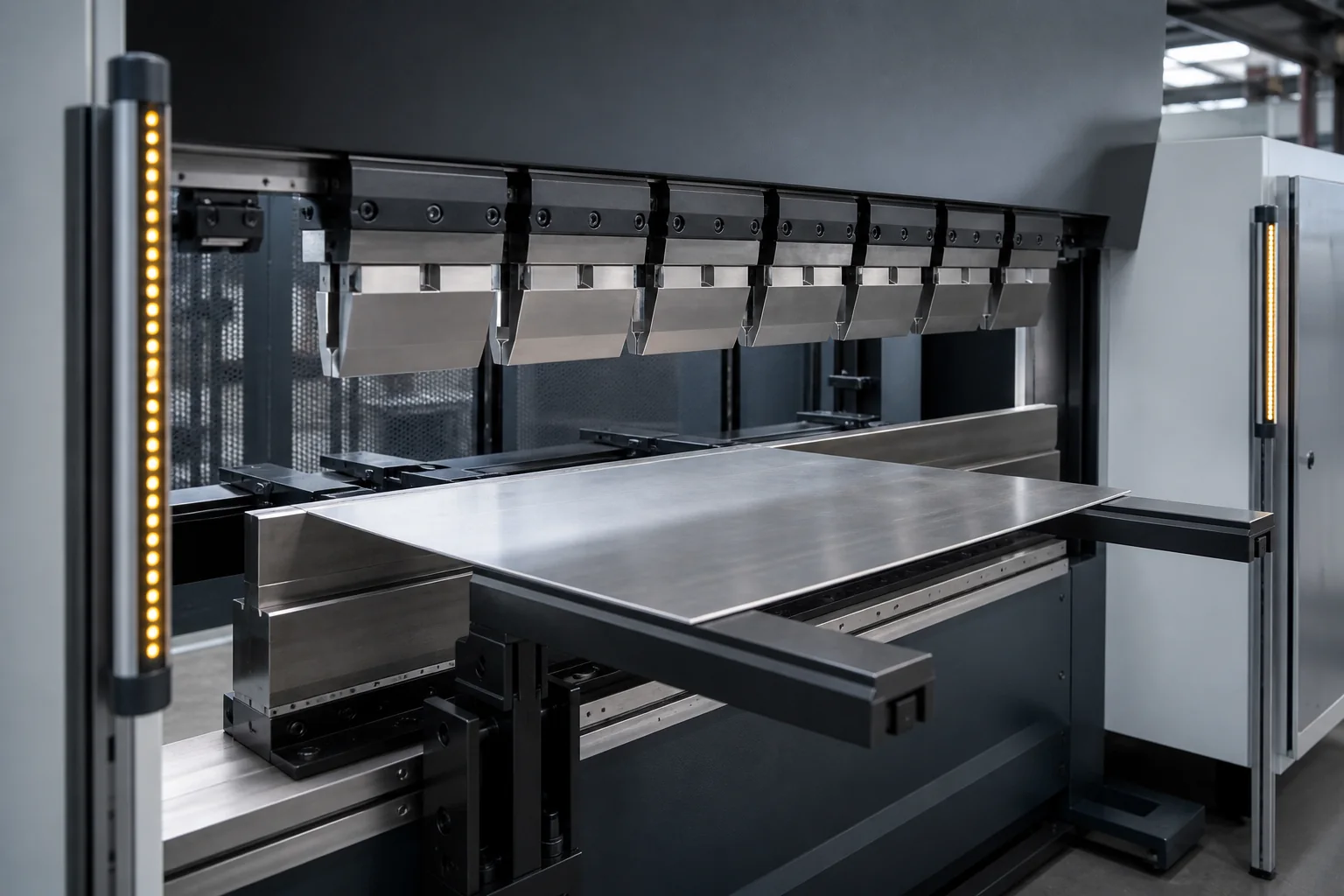
Illustrative generic sheet-forming setup with a stainless blank resting on support arms between open segmented upper tooling and a V-die
Illustrative sheet-forming process referenceSheet Metal Fabrication

Capability review

This page describes common request types. Available processes, equipment, tolerances, inspection, documentation, and fulfillment are confirmed for each quote.

Overview

A formed sheet part needs one controlled relationship between the flat blank and final geometry.

A flat pattern is a manufacturing definition derived from the formed shape, sheet thickness, inside bend radii and angles, and the stated bend-development method. Bend allowance, bend deduction, K-factor, and a bend table are alternative ways to define or calculate developed length; one should not be assumed from a model without knowing which definition controls. During bending, material stretches on the outside and compresses on the inside, while material properties, thickness variation, grain direction, bend orientation, springback, tooling contact, flange length, nearby features, and sequence can affect the released shape. Holes, slots, tabs, notches, bend and corner reliefs, seams, hardware, welds, finish build, and masking can also change forming, access, fit, and inspection. The request should tie the flat and formed files, cut and edge features, every bend and flange, mating interfaces, downstream operations, measurement condition, and acceptance criteria to one drawing revision. These inputs support project-specific review; they do not establish a cutting or forming method, universal bend value, achieved geometry, burr condition, installed hardware, weld or finish result, inspection record, availability, or fulfillment route before quoting.

Material and flat definition

Identify the governing formed model, drawing and flat-pattern revision; sheet, coil or supplied-blank context; exact material specification and grade; thickness or gauge designation plus actual thickness; temper, hardness or condition; mill finish or protective film; grain or rolling direction when controlled; flat-development method; and supplied-material status.

Bends, flanges, reliefs, and sequence

Define each bend line or tangent convention, inside radius, angle convention and target angle, direction, sequence, bend allowance, deduction, K-factor or bend-table basis when prescribed, flange and return dimensions, hems and offsets, relief geometry, hole-to-bend relationships, and restrained or free-state measurement condition.

Interfaces, final condition, and acceptance

State cut-edge and burr requirements, controlled chamfers or edge breaks, holes, slots, tabs and notches, hardware identity and mounting condition, seams and weld joints, mating datums, clearance and fit, finish and masking boundaries, cosmetic faces, inspection method and coverage, acceptance and rejection criteria, preservation, packaging, and requested record fields.

Fulfillment review

Requests are reviewed manually. The fulfillment route and availability are confirmed before acceptance.

Quote inputs

The information that starts a useful sheet metal fabrication review.

The quote form accepts private files or a written project description, plus optional process, material, material-source, quantity, and timing details. Select Sheet metal in the optional Process field when useful, then describe the controlled flat and formed definitions and any adjacent weld, finish, hardware, assembly, or inspection scope.

Controlled files, material, and incoming condition
Formed STEP or STP model and matching PDF drawing, controlled flat-pattern DXF or DWG when available, drawing and flat revision, units, quantity, material specification and grade, sheet, coil or supplied-blank form, thickness or gauge designation and actual thickness, temper, hardness or other material condition when relevant, mill finish, coating or protective film, grain or rolling direction when controlled, material source, and any incoming flatness, damage or surface condition relevant to the request
Flat profile, cut features, edges, and reliefs
Controlling outside profile; holes, slots, cutouts, notches, tabs, lances or other formed and cut features when specified; corner, bend and seam relief shape and dimensions; feature-to-edge and feature-to-bend relationships; cut-edge quality definition when governed; burr direction or limit; required edge break, chamfer or radius; edges that remain sharp; cosmetic and protected surfaces; and dimensions that apply in the flat state
Bends, flanges, formed dimensions, and sequence
Each bend identifier, line or tangent convention, inside bend radius, bend angle and angle convention, bend direction, order and sequence, flange, return, hem, curl, jog or offset definition when present, inside and outside formed dimensions, bend allowance, bend deduction, K-factor, bend table or other unfold rule when controlled, grain relationship, springback-compensation basis when prescribed, short-flange and access-sensitive features, hole-to-bend distance, formed configuration, and restrained or free-state measurement condition
Interfaces, downstream scope, acceptance, quantity, and timing
Hardware part numbers and supplier instructions, self-clinching or other insert and fastener locations, mounting-hole and sheet-condition requirements, installation direction, seams and joints, weld definition and fit-up, mating parts and datums, clearance and fit, finish, preparation and masking boundaries, cosmetic faces, flat- and formed-state inspection methods and locations, acceptance and rejection criteria, coverage or sampling, nonconformance instruction, requested record fields and deliverable boundary, preservation and packaging, quantity, and target timing
Interactive request review

Explore the relationships that connect the flat blank to the formed part.

Select a review point on the fixed flat-and-formed layout to see how cut features and reliefs, bend and flange geometry, and hardware, mating, finish, inspection, and protection requirements should remain tied to one controlled definition.

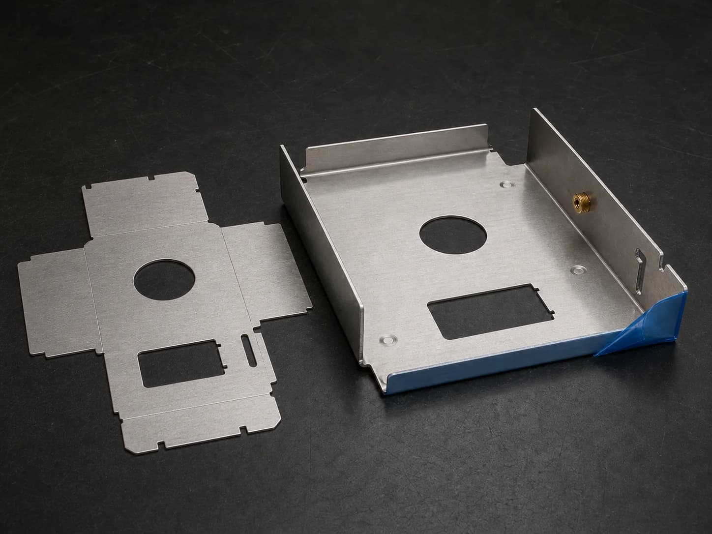
Illustrative sheet-metal planning layout with a matching stainless flat blank and formed chassis showing cutouts and reliefs, two bend-and-flange relationships, and a self-clinching insert beside a protected mating edge

Matching blank and chassis, three review zones

Cut features, formed relationships, and interface or finish boundaries remain visible together while the request details change.

Illustrative example only; markers locate topics for review. They do not establish the controlling revision, obtained geometry, achieved edge or finish, installed hardware result, interface result, inspection decision, package status, project route, or capability.

Sheet metal fabrication review

What should the sheet metal definition explain?

Select a review feature to see the details that help clarify the request.

Flat-pattern profile, cut features, reliefs, and edge condition

Define the controlling flat pattern or formed model, outside profile, holes, slots, notches, tabs, corner and bend reliefs, edge-break requirements, and which dimensions apply before or after forming.

  • Controlling flat pattern, formed model, drawing revision, and the convention for dimensions that apply before or after forming
  • Outside profile, holes, slots, notches, tabs, corner reliefs, bend reliefs, and their controlling datums
  • Cut-edge condition, edge-break requirement, burr direction or residual condition, and protected feature boundaries

Helpful sheet metal detail

Connect the flat and formed definitions, then label the profile, every cut feature and relief, the dimensions that apply before or after forming, and each required edge condition.

Start with your sheet metal files
Material, process and sequence fit, achievable blank, bend, edge, interface, finish, inspection and packaging requirements, hardware responsibility, fulfillment path, availability, and timing are confirmed from the submitted information during quote review.

Capabilities

Common sheet metal fabrication request patterns, kept easy to scan.

These examples organize the starting point. Cutting and forming method, process and material fit, achievable geometry and edge condition, sequence, hardware and joint scope, finish and inspection requirements, requested records, fulfillment, and timing are confirmed from the project files.

Flat blanks, profiles, openings, tabs, and relief requests

Flat definition

Requests reviewed from the formed and flat revisions, material specification and condition, thickness, grain direction, outside profile, holes, slots, cutouts, notches, tabs, lances or other specified features, corner and bend reliefs, feature-to-edge and feature-to-bend relationships, cut-edge and burr requirements, dimensions controlled in the flat state, and inspection method.

Brackets, panels, channels, guards, covers, and multi-bend chassis requests

Formed geometry

Requests reviewed from every bend identifier, radius, angle and direction; bend-line or tangent convention; flange, return, hem, curl, jog or offset dimensions when present; inside and outside formed dimensions; allowance, deduction, K-factor, bend table or unfold rule when controlled; grain relationship; sequence; access-sensitive features; springback basis when prescribed; and formed-state acceptance.

Hardware, seams, welds, and assembly-interface requests

Interfaces & joints

Requests reviewed from exact insert, fastener and hardware identities, supplier instructions, mounting-hole and sheet condition, installation direction, seams, tabs and slots, weld joint and fit-up definition, adhesive or retention notes, mating parts and datums, clearance and fit, access, assembly sequence, protected surfaces, and inspection criteria.

Edge, finish, cosmetic, inspection, preservation, and packaging requests

Final condition

Requests reviewed from burr and edge-break definitions, cosmetic and protected surfaces, surface preparation, coating or finish specification, masking and coating-free regions, pre- and post-finish dimensional intent, flat or formed inspection state, datums, method, coverage, acceptance and rejection criteria, identification, requested record fields, preservation, package configuration, separation, and handling restrictions.

Quote workflow

From controlled flat and formed definitions to a confirmed fabrication path.

A short, human-managed review keeps material, cut features, bends, interfaces, downstream operations, inspection state, acceptance, and open questions visible before work is accepted.

  1. 01

    Share the controlled flat and formed definitions

    Upload the formed model and drawing, flat definition when available, material specification and thickness, grain or rolling direction, cut and edge features, bends, flanges and reliefs, hardware and joint details, weld and finish boundaries, inspection and acceptance criteria, quantity, and target timing.

  2. 02

    Reconcile material, flat, bend, and interface drivers

    File and revision consistency, material form and condition, thickness, grain direction, flat-development basis, cut features, edge requirements, bend radii, angles and directions, flange and relief geometry, sequence, hardware and mounting conditions, seams, welds, mating interfaces, finish and masking, measurement state, acceptance, and requested records are organized for follow-up.

  3. 03

    Confirm the project path

    Cutting and forming method, process and material fit, achievable flat and formed geometry, edge and surface condition, sequence, hardware and joint scope, weld and finish requirements, inspection method and coverage, requested record fields, fulfillment, timing, and remaining questions are resolved before acceptance.

  4. 04

    Coordinate the approved baseline

    Once a request is accepted, the controlled formed model, drawing and flat revisions, material and thickness, grain orientation, profile and cut features, edge and relief definitions, bend data and sequence, hardware and joint identities, mating interfaces, weld, finish and masking boundaries, measurement condition, acceptance criteria, requested records, quantity, timing, and authorized changes become the reference point for project communication.

Request readiness

Small decisions that make sheet metal fabrication requests easier to review.

Clear flat-development, bend, interface, sequence, and acceptance intent is more useful than assuming a standard radius, K-factor, process, or formed result.

Design intent before assumptions
  1. 01

    Keep the formed model, drawing, and flat definition revision-aligned.

    Identify the controlling file and revision for the formed part and flat pattern, units, any intentionally added manufacturing features, and how changes propagate. A separately edited flat file can conflict with the formed definition unless the authority and change rule are explicit.

  2. 02

    State material product form, thickness, condition, and grain direction.

    Provide the governing material specification and grade, sheet, coil or supplied-blank context, gauge designation and actual thickness, temper, hardness or other condition when relevant, mill finish or protective film, source status, and rolling or grain direction where bend orientation, appearance, or function makes it controlled.

  3. 03

    Define one bend-angle and flat-development convention.

    For each bend, identify the bend line or tangent convention, inside radius, bend angle and whether it is an included, open or rotation angle, direction, inside or outside formed dimensions, and the controlling allowance, deduction, K-factor, bend table or other unfold rule. Do not mix conventions without a stated precedence.

  4. 04

    Show flanges, returns, reliefs, nearby features, and sequence together.

    Dimension flange, return, hem, curl, jog or offset geometry when present; locate holes, slots, tabs and notches relative to bend zones and tangencies; define corner and bend reliefs; identify short or return flanges and access-sensitive features; and state bend order, handedness, protected faces, and any free- versus restrained-state condition.

  5. 05

    Define hardware, joints, welds, and finish as interface requirements.

    Provide exact self-clinching, riveted, threaded or other hardware identities and supplier instructions, mounting-hole and sheet condition, installation direction, seams and tab-slot relationships, weld joint and fit-up, mating parts and datums, clearance, adhesive or retention notes, finish and masking boundaries, cosmetic faces, sequence, and access.

  6. 06

    Tie acceptance to the flat or formed measurement state.

    State which profile, hole, flange, angle, overall, interface, edge, finish and cosmetic requirements are checked flat, formed, free, restrained, before finish or after finish; then define datums, support, method, locations, coverage, acceptance and rejection criteria, nonconformance instruction, requested record fields, preservation, packaging, and handling restrictions.

Materials

Common sheet-material contexts for fabrication review.

Material identity is one layer of the request. Exact specification, grade, thickness, temper or condition, product form, grain direction, incoming surface, bend and edge definitions, joint and finish compatibility, inspection, supplied-material context, and availability are confirmed for each project.

Material guide

Aluminum

Bracket, cover, panel, tray, guard, chassis and enclosure requests where alloy and temper, sheet or supplied-blank form, actual thickness, mill or protected surface, rolling direction, bend orientation and radius, flat-development basis, reliefs, cut edges, hardware, weld or adhesive joints, finish and masking, cosmetic faces, formed-state inspection, and packaging need review.

5052-H32 · 3003-H14 · 6061-T6 examples

View material
Material guide

Stainless steel

Panel, guard, cover, bracket, tray, housing and chassis requests where exact grade and condition, cold-rolled or other sheet definition, thickness, surface finish and protective film, grain or polish direction, bend radius and sequence, springback basis, edge and burr condition, seams and welds, hardware, finish or passivation sequence, cosmetic faces, inspection, and protected handling need review.

304 · 316/316L · 430 examples

View material
Material guide

Copper

Shield, contact, bus, cover, bracket, enclosure detail and formed-conductor requests where alloy and temper, sheet thickness, conductivity or contact-surface context, rolling direction, bend radius and sequence, hole and relief geometry, cut edges, joining and hardware, plating or coating boundaries, oxidation protection, formed-state inspection, and packaging need review.

C10100 · C11000 · C12200 examples

View material
Material guide

Brass

Bracket, contact, shield, trim, cover, spring-detail and enclosure requests where alloy and temper, sheet thickness, grain direction, bend orientation and radius, flat-development basis, relief and edge condition, hardware and mating interfaces, solder, braze, weld or adhesive joint notes when specified, finish and masking, cosmetic surfaces, inspection, and protected handling need review.

C26000 · C27200 · C46400 examples

View material

FAQ

Sheet metal fabrication quote questions.

Start with a private formed STEP or STP model and matching PDF drawing, a controlled flat-pattern DXF or DWG when available, or a written project description. Add drawing and flat revision, units, material specification and grade, thickness or gauge and actual thickness, temper or condition, grain direction, cut and edge features, every bend and flange, allowance or unfold basis when controlled, reliefs, hardware, seams and joints, weld, finish and masking, inspection and acceptance criteria, quantity, and timing. Select Sheet metal in the optional Process field when useful.

The formed model communicates final geometry and interfaces; the flat pattern communicates the developed blank, bend lines, reliefs, and manufacturing cut definition. They must reference the same revision and material rule. State which file controls, whether the flat was derived or intentionally edited, and how bend allowance, deduction, K-factor, a bend table, or another unfold rule was applied so conflicting geometry is not silently assumed.

Identify each bend and its inside radius, bend line or tangent convention, angle and angle convention, direction, sequence, flange or return dimensions, hems, curls, jogs or offsets when present, inside or outside dimension basis, grain relationship, controlled allowance or springback-compensation basis when prescribed, and whether acceptance is measured free or restrained. Avoid a generic bend note that leaves the angle or dimension convention unclear.

Locate holes, slots, notches, tabs and other features relative to bend zones, tangencies and edges; define bend, corner and seam reliefs; provide exact hardware and mounting-hole requirements; show seams, joints, tabs, slots and weld fit-up; identify mating datums and access; and map preparation, finish, masking, cosmetic faces and protected surfaces. State the intended cutting, forming, hardware, joining and finish sequence rather than expecting it to be inferred.

Inspection and documentation requirements can be reviewed during quoting. No certification or report package is implied until confirmed.

Requests are reviewed manually. The fulfillment route and availability are confirmed before acceptance.

Start with the files you have

Ready to review your sheet metal fabrication request?

Share the controlled formed model, drawing and flat definition, material and thickness, grain direction, cut and edge features, bend and flange data, reliefs, hardware and joint details, weld and finish boundaries, inspection state and acceptance criteria, preservation and packaging notes, requested records, quantity, and timing. Pearson will follow up on the details that still need confirmation.

Request a sheet metal quote