Component role before method
Tube sheets, baffles, support plates, flanges, nozzles, end plates, and replacement components begin with different functional and assembly questions.
Heat exchanger machining services
Tube sheets, baffles, support plates, flanges, and nozzles raise review questions around plate condition, hole definition, sealing faces, datums, bolting, mating context, and inspection. Share the model and drawing so those requirements can be organized and the project path confirmed before acceptance.
Capability review
This page describes common request types. Available processes, equipment, tolerances, inspection, documentation, and fulfillment are confirmed for each quote.
Overview
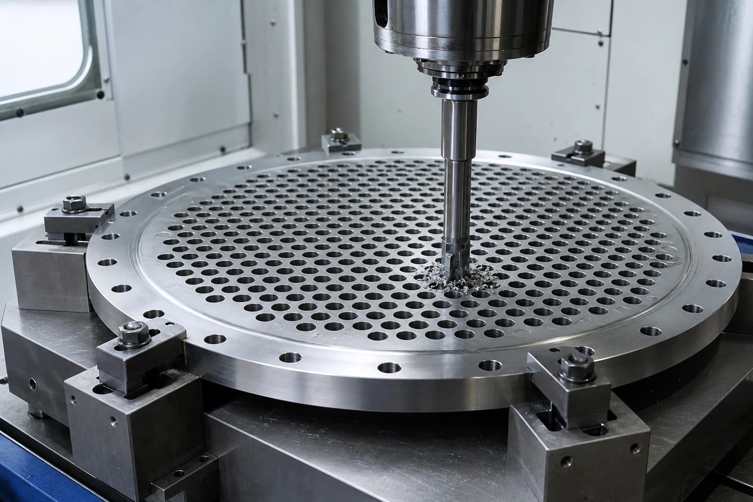
A dense hole field is only one part of a tube-sheet request. Component role, tube-hole geometry and joint intent, pitch and ligament, pattern orientation, pass-lane and tie-rod features, bolt-circle relationships, gasket or sealing faces, plate condition, mating assembly, governing drawing, and inspection intent should be visible before a process path is selected.
Tube sheets, baffles, support plates, flanges, nozzles, end plates, and replacement components begin with different functional and assembly questions.
Tube holes, bolt holes, tie-rod features, pass lanes, faces, and orientation details need a clear shared datum and clocking strategy.
Grade, form, current condition, cladding, mating tube or bundle details, sequence, finish, and documentation expectations belong in the request instead of being inferred.
Fulfillment review
Requests are reviewed manually. The fulfillment route and availability are confirmed before acceptance.
Quote inputs
You do not need every answer before submitting. Share what is known and mark the rest for follow-up.
Interactive tube-sheet review
Select a feature on the sample tube sheet to see what the model, hole map, and drawing should communicate before the project path is confirmed.
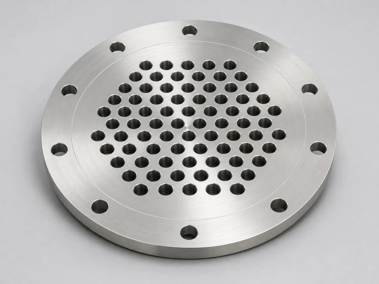
Sample tube-sheet feature map
The numbered markers match the review features and guidance panel.
Illustrative example only; markers identify review areas, not dimensions, codes, or tolerances.
Tube-sheet feature review
Choose a feature group to see the details that help clarify the request.
The hole map should distinguish the tube field from every other opening and show the pitch, orientation, and remaining material relationships that control the component.
Helpful drawing detail
Include a hole table, detail view, or DXF when useful, and identify every feature that differs from the repeating tube-hole pattern.
Process fit, equipment fit, achievable tolerances, inspection, documentation, fulfillment, and timing are confirmed from the project information during quote review.
Capabilities
These examples help identify the likely starting point. Process fit, equipment fit, achievable tolerances, and availability are confirmed from the project files.
Circular and other plate requests reviewed from the tube-hole map, pitch, ligament, pass lanes, tie-rod or plug features, bolt circle, faces, edge details, and datum relationships.
Plate and segment requests reviewed from their tube clearances, cut geometry, support or orientation features, edge condition, material state, and relationship to the bundle layout.
Connection-component requests reviewed from their bore, bolt pattern, face, groove, bevel, clocking, datum, mating-part, weld-preparation, and sealing requirements.
Grade and form, current or clad condition, cleanup allowance, surface and edge requirements, critical relationships, documentation, and inspection expectations reviewed together.
Quote workflow
A short, human-managed review keeps patterns, faces, assembly relationships, and open questions visible before work is accepted.
Upload the model, drawing, hole map, photos, quantity, material grade or preference, and known assembly or functional requirements.
Component role, pattern, plate condition, hole and joint definition, datums, sealing faces, mating context, sequence, and inspection intent are organized for follow-up.
Process fit, equipment fit, achievable tolerances, fulfillment, timing, and remaining questions are resolved before acceptance.
Approved files and requirements become the reference point for project communication and requirement control.
Drawing readiness
Clear component, pattern, assembly, and governing-design intent is more useful than assuming a method or applying close requirements everywhere.
State whether the part is a tube sheet, baffle, support plate, flange, nozzle, end plate, or replacement component, and identify the controlling drawing revision and customer specification or code requirements.
Distinguish tube holes from bolt, tie-rod, plug, vent, drain, and other features, and include count, pitch, layout, excluded areas, and orientation information.
Define how the tube field, bolt circle, pass lanes, partition features, faces, nozzles, or shell orientation relate instead of relying on the visual centre of the plate.
State size, depth or through condition, groove, chamfer, edge, surface, allowance, and tube-to-tube-sheet joint information where those details are functionally required.
Identify gasket or sealing geometry, functional face, finish and flatness intent, starting condition, cleanup allowance, finished side, and any protected areas.
Name the grade, form, current condition or cladding, planned fabrication or finishing sequence, functional inspection points, and required documentation without treating every feature as equally critical.
Materials
Grade, form, current condition, cladding, finish, and availability are confirmed for each request.
Tube-sheet, baffle, flange, and connection-component requests where the exact grade, form, current condition, cladding, pattern, face, and finish belong in the review.
304 · 316/316L · duplex examples
View materialTube-sheet, plate, ring, and connection-detail requests where the exact copper grade, stock form, hole pattern, surface intent, and mating context need review.
C110 · C145 · C101 examples
View materialTube-sheet, plate, baffle, and fitting-related requests where the exact alloy, starting condition, feature geometry, finish, and assembly context should be identified.
C360 · C260 · C464 examples
View materialPlate, flange, end-cover, and general exchanger-component requests where grade, stock condition, pattern, datum, sealing, and finish requirements need review.
6061 · 5052 · tooling plate examples
View materialContinue exploring
Review plate faces, slots, pockets, bolt patterns, datum relationships, and surrounding milled features.
Review tube and bolt-hole patterns, tapped features, counterbores, countersinks, chamfers, and access requirements.
Review functional faces, final thickness, flatness, parallelism, datum, and surface-finish requirements.
Review datums, hole fields, bolt circles, sealing faces, critical relationships, and documentation expectations.
See common exchanger, process-equipment, flange, nozzle, tube-sheet, and replacement-component request contexts.
See common exchanger, condenser, cooler, support-plate, and replacement-component request contexts.
FAQ
A STEP or STP model and matching PDF drawing are a strong starting pair. Add a DXF or hole table when it clearly defines the pattern, plus component role, material and current condition, raw and finished dimensions, mating context, quantity, timing, governing drawing or specification, and inspection or documentation needs.
Provide a readable hole map or table that identifies tube-hole size and type, count, layout, pitch, orientation, excluded areas, ligament intent, and which features are bolts, tie rods, plugs, vents, drains, or partition-related details.
State the size, depth or through condition, grooves, chamfers, edges, surface requirements, and allowances that matter. Include the customer-defined tube-to-tube-sheet joint intent and mating-tube information where it affects the component.
Identify the functional sealing or gasket face, geometry, finish and flatness intent, primary datums, bolt-circle origin, clocking, and relationships among the tube field, pass lanes, partition features, nozzles, shell, or mating component.
State the controlling drawing revision, customer specification or code requirements, material grade and condition, cladding, planned sequence, critical features, and required inspection or documentation. Applicable requirements and the final scope are confirmed from the project files.
Requests are reviewed manually. The fulfillment route and availability are confirmed before acceptance.
Start with the files you have
Share the model, drawing, hole map, photos, material condition, mating context, and known requirements. Pearson will follow up on the details that still need confirmation.
Request a heat-exchanger quote