Working geometry and product intent
Punch, die opening, core, cavity, forming, cutting, trim, and shutoff features should be connected to the governed product geometry and functional result instead of reviewed in isolation.
Tool and die making services
Punches, die inserts, mold cores and cavities, tooling plates, wear components, replacement details, and repair requests depend on more than a finished product shape. Share the tool and governed product function, material grade, hardness or heat-treatment condition, current condition, working faces, clearance or shutoff relationships, insert and component boundaries, datums and guide relationships, mounting interfaces, service access, planned sequence, finish, inspection, revision, and repair context so the request can be organized and a project path confirmed before acceptance.
Capability review
This page describes common request types. Available processes, equipment, tolerances, inspection, documentation, and fulfillment are confirmed for each quote.
Overview
A useful tooling request connects the tool assembly to the product geometry and operation it governs. It identifies working faces and edges, clearance or shutoff intent, core and cavity boundaries, insert and component relationships, functional datums, guide and locating features, mounting interfaces, material and current condition, sequence, service access, revision history, finish, repair intent, and the characteristics that need acceptance review.
Punch, die opening, core, cavity, forming, cutting, trim, and shutoff features should be connected to the governed product geometry and functional result instead of reviewed in isolation.
Tool plates, datum surfaces, guide features, insert pockets, retainers, fasteners, mounting interfaces, clearances, and component boundaries should be explicit in the assembly files.
Wear, damage, prior changes, retained geometry, replacement or spare intent, service access, revision control, planned sequence, finish, and inspection requirements belong in the request.
Fulfillment review
Requests are reviewed manually. The fulfillment route and availability are confirmed before acceptance.
Quote inputs
You do not need every answer before submitting. Share what is known and mark the rest for follow-up.
Interactive tooling review
Select a feature on the open modular die set to see what the assembly, component, product, and requirement files should communicate before the project path is confirmed.
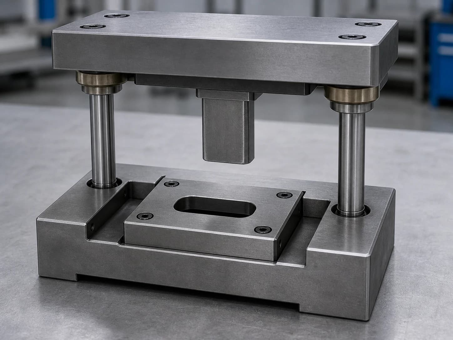
Tooling relationship map
The numbered markers connect the sample tooling relationships to the guidance panel.
Illustrative example only; markers identify request-review areas, not original dimensions, material, hardness, working clearance, inspection approval, or tooling qualification.
Tool and die review
Select a review feature to see the details that help clarify the request.
The punch definition should connect its complete working profile and faces to the governed product or operation, retained feature, material direction, and assembly references.
Helpful drawing detail
Include a section or detail where useful, then identify the complete profile, retained side, material direction, working faces, and functional datum references.
Capabilities
These examples help identify the likely starting point. Process fit, equipment fit, achievable requirements, material and sequence needs, inspection scope, fulfillment, and availability are confirmed from the project files.
Punch, die opening, insert, cutting-edge, trim, pierce, form, stripper, retainer, wear-detail, and replacement requests reviewed from the governed product, working profile, clearance intent, material and current condition, component relationships, datums, service access, sequence, finish, and inspection intent.
Core, cavity, insert, slide, lifter, shutoff, pocket, retainer, and replacement-detail requests reviewed from the governed product geometry, draft or parting intent when defined, interfaces, locating references, service access, material condition, sequence, finish, and acceptance requirements.
Tool plate, shoe, fixture, nest, locator, guide, bushing, mounting, fastening, spacer, retainer, and support-component requests reviewed from their assembly function, datum scheme, interface geometry, access, revision, material condition, finish, and inspection intent.
Worn, chipped, cracked, distorted, incomplete, obsolete, coated, or modified-tooling requests reviewed from current condition, intended repair or replacement, retained and protected geometry, component history, approved revision, planned sequence, finish, critical characteristics, and inspection or documentation needs.
Quote workflow
A short, human-managed review keeps the governed product, working geometry, component relationships, current condition, sequence, and open questions visible before work is accepted.
Upload the tool assembly and component files, governed product model and drawing, layouts, photos, material and current condition, quantity, revision history, sequence, repair or replacement intent, and known finish or inspection requirements.
Working profiles and faces, clearance or shutoff relationships, inserts and interfaces, functional datums, guides and locators, mounting, service access, material and hardness condition, current wear or damage, planned sequence, finish, and acceptance criteria are organized for follow-up.
Process fit, equipment fit, achievable requirements, material and heat-treatment sequence, sample-review needs, inspection method and scope, fulfillment, timing, and remaining questions are resolved before acceptance.
Approved assembly, component, product, revision, and requirement files become the reference point for project communication and requirement control.
Request readiness
Clear assembly, product, and service intent is more useful than assuming a method, sequence, material response, or acceptance approach.
Share the complete tool assembly and component files alongside the product model and drawing, operation or layout context, mating information, revision state, and the features each tooling component controls.
Identify punch and die profiles, cutting or forming edges, core and cavity surfaces, shutoffs, parting or trim intent, permitted reliefs, clearance relationships, edge requirements, and the product geometry that governs them.
Show which faces, holes, bores, pins, guide posts, bushings, keys, locators, plates, or shoulders establish alignment and connect every critical tool-to-component and tool-to-product relationship to those references.
Define replaceable insert and pocket boundaries, retainers, fasteners, standard-component interfaces, removal directions, protected surfaces, keep-clear regions, adjustment intent, and access needed for assembly or service.
Identify the grade, hardness or heat-treatment condition, stock or current condition, allowance, and which dimensions, working faces, or interfaces are established before or after any specified EDM, surface grinding, heat treatment, coating, or finishing step.
Identify the working, locating, guiding, mounting, mating, and product relationships that need verification; distinguish repair from replacement or spare intent; state the approved revision, acceptance criteria, measurement condition, and documentation needs.
Materials
Grade, form, current condition, hardness or heat-treatment sequence, finish, inspection needs, and availability are confirmed for each request.
Punch, die insert, cutting and forming detail, core, cavity, wear component, locator, guide, replacement, and repair requests where grade, hardness or heat-treatment condition, allowance, sequence, working geometry, finish, and inspection intent need review.
A2 · D2 · O1 · H13 examples
View materialInsert, core, cavity, plate, fixture, guide, locator, interface, replacement, and repair-related requests where the exact grade, current condition, working geometry, sequence, finish, and inspection context belong in the review.
303 · 304 · 316/316L examples
View materialTool plate, fixture, nest, locator, adapter, setup aid, prototype-tooling, insert, and replacement-detail requests where grade, stock form, datum, interface, working feature, edge, finish, and inspection intent need review.
6061-T6 · 7075-T6 · MIC-6 examples
View materialElectrode, insert, contact, interface, heat-transfer-detail, fixture, and tooling-component requests where the exact alloy, stock form, geometry, sequence, surface, finish, handling, and inspection requirements need review.
C110 · C145 · C101 examples
View materialContinue exploring
Review tooling profiles, through cuts, blind cavities, start features, inserts, electrode context, material condition, finish, and datum requirements.
Review tool plates, bases, fixtures, pockets, profiles, holes, inserts, cores, cavities, datum relationships, sequence, finish, and inspection requirements.
Review planar working faces, datum intent, stock or current condition, flatness and parallelism requirements, finish, sequence, and inspection context.
Review working, locating, guiding, mounting, mating, and product relationships, measurement conditions, acceptance criteria, coverage or sampling, and documentation requirements.
Review worn, chipped, cracked, distorted, modified, obsolete, or out-of-requirement tooling and the evidence needed to define the intended repair or replacement.
See common core, cavity, insert, plate, locator, fixture, replacement, and repair request contexts for polymer-processing equipment and tooling.
FAQ
A tool assembly model, component models, matching PDF drawings, and the governed product model and drawing are a strong starting set. Add layouts or operation context, material and hardness or heat-treatment condition, current wear or damage, working and locating relationships, revision history, sequence, finish, repair or replacement intent, inspection or documentation needs, quantity, and target timing when known.
Punches, die inserts, cutting and forming details, mold cores, cavities, slides, lifters, replaceable inserts, tool plates, shoes, fixtures, locators, guides, retainers, wear components, spares, replacements, revisions, repairs, and sample-led recreations may be submitted. Process fit, equipment fit, achievable requirements, material and sequence needs, inspection scope, fulfillment, and availability are confirmed from the project information.
Show the governed product geometry, working faces and edges, punch-to-die clearance or core-to-cavity and shutoff intent, component and insert boundaries, pockets and retainers, functional datums, guide and locating references, mounting interfaces, access, material condition, planned sequence, finish, and acceptance requirements.
Multiple clear views, a reference scale, key measurements, assembly and product context, revision information, and notes about wear, damage, prior changes, retained geometry, and intended function can begin the review. Additional measurements, models, drawings, or an approved requirement record may be needed before acceptance; sample-review availability is confirmed during quoting.
State the material grade, hardness or heat-treatment condition, current condition, planned sequence, which working or interface features are final before or after each specified step, finish areas, functional datum relationships, acceptance criteria, measurement condition, and documentation needs. Process fit, equipment fit, achievable requirements, material and sequence needs, inspection method and scope, fulfillment, and availability are confirmed during quote review.
Requests are reviewed manually. The fulfillment route and availability are confirmed before acceptance.
Start with the files you have
Share the tool assembly, component and governed-product files, layouts, photos or sample condition, material, component relationships, revision, planned sequence, finish, repair or replacement intent, and inspection requirements. Pearson will follow up on the details that still need confirmation.
Request a tooling quote