CNC tube bending services

CNC tube bending requests, organized around tube condition, bend geometry, plane relationships, and acceptance limits.

A tube model does not by itself define the starting stock or how each bend is controlled. Share whether the size is actual tube outside dimension or nominal pipe size and schedule; profile, outside dimensions and wall; material specification, grade and condition; welded or seamless construction and seam orientation when controlled; centerline radii, angles, tangent points, straight and end lengths; length-rotation-angle (LRA/YBC) or XYZ coordinate convention; rotations, bend planes, handedness and end clocking; nearby features and mating interfaces; allowable ovality, flattening, wall thinning, wrinkling, collapse, cracking and surface marking; finished centerline, end-position and inspection requirements; quantity and timing so process, tooling, measurement and fulfillment fit can be confirmed before acceptance.

  • Tube, wall, and material definition
  • CLR, angle, rotation, and end geometry
  • Scope confirmed per quote
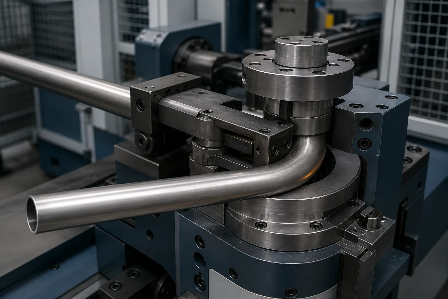
Illustrative generic guarded rotary-draw tube-bending setup with a round metal tube partially wrapped around a bend die between the clamp and pressure-die tooling
FIG. 01 — ILLUSTRATIVE ROTARY-DRAW TOOLING CONTEXTCNC Tube Bending

Capability review

This page describes common request types. Available processes, equipment, tolerances, inspection, documentation, and fulfillment are confirmed for each quote.

Overview

A bent tube is controlled by more than its finished centerline shape.

Tube bending plastically forms straight tube into specified angles, radii, and three-dimensional paths. Around a bend, the extrados is stretched and may thin, the intrados is compressed and may wrinkle, and a round cross-section may flatten or become oval; springback can change the released angle and radius. Material specification and condition, actual outside dimensions and wall, profile orientation, weld-seam position, centerline-radius-to-section and outside-diameter-to-wall relationships, straight grip and tangent lengths, bend sequence, tooling contact, and material variation all influence the review. A finished model should therefore be paired with the starting-stock definition, bend-coordinate convention, controlled end geometry, permissible deformation and marking, and an inspection state and datum scheme. These inputs support a project-specific review; they do not establish an accepted process, tool set, tolerance, result, documentation package, availability, or fulfillment route.

Starting tube and material condition

Identify actual tube outside dimensions and wall or nominal pipe size and schedule, round or shaped profile, material specification, grade and condition, welded or seamless construction, weld-seam orientation when controlled, finish, supplied-stock source, and any lot-consistency or surface-protection requirement.

Bend path, planes, and end relationships

Define every centerline radius, bend angle, tangent point, straight and end length, distance between bends, feed or length convention, rotation sign, plane of bend, bend direction and order, handedness, end clocking, trim basis, nearby features, and mating-interface datums.

Deformation and inspection boundaries

State allowable ovality or flattening, minimum wall or wall-thinning limit, wrinkles, kinks, collapse, cracking, tooling or grip marks, surface damage, finished centerline or profile, bend angle and radius, end position and orientation, free or restrained inspection state, datum scheme, method, coverage, and requested records.

Fulfillment review

Requests are reviewed manually. The fulfillment route and availability are confirmed before acceptance.

Quote inputs

The information that starts a useful CNC tube bending review.

The quote form accepts private files or a written project description, plus optional process, material, material-source, quantity, and timing details. Tube bending is not a dedicated process choice in the current intake, so leave Process unset or select Other when useful and name CNC tube bending in the description.

Starting tube and material condition
Finished-part STEP or STP model and matching PDF drawing when available, drawing number and revision, tube or pipe designation, actual outside diameter and wall or nominal pipe size and schedule, round, square, rectangular or other profile dimensions and corner radii, material specification, alloy or grade, temper, heat-treatment or hardness condition when applicable, welded or seamless construction, weld-seam location and orientation when controlled, coating or finish condition, marking restrictions, supplied-stock source, and any lot-consistency requirement
Bend geometry and coordinate convention
Finished centerline path, centerline radius (CLR) for each bend, bend angle and direction, tangent points, tangent-to-tangent distance or distance between bends (DBB), straight lengths, start and finish end lengths, overall and developed length basis, bend allowance or trim basis when specified, bend order, handedness, and either length-rotation-angle (LRA/YBC), XYZ coordinates, or another clearly defined convention with origin, axes, units, rotation sign, and plane-of-bend reference
Ends, nearby features, and mating interfaces
Start and finish end identity, end-face angle and clock orientation, cut and trim condition, flare or other end form when specified, holes, slots, notches, copes, brackets, bosses, fittings and attachment points, feature-to-tangent relationships, before-or-after-bend intent, protected and cosmetic surfaces, assembly datums, insertion depth, clearance, fit-up, mating parts, weld or attachment definition, finishing sequence, and handling or packaging notes
Acceptance, inspection, quantity, and timing
Finished centerline, profile, bend-angle, centerline-radius, distance-between-bends, end-to-end, end-position and end-orientation requirements; allowable ovality or flattening and its calculation; minimum wall or maximum wall-thinning basis; allowable wrinkles, kinks, collapse, cracking, weld-seam movement, tooling or grip marks and surface damage; free-state or restrained inspection condition; datum and fixture scheme; measurement method and locations; coverage or sampling; acceptance and rejection criteria; nonconformance instruction; requested record fields and deliverable boundary; quantity; and target timing
Interactive request review

Explore the tube, bend, and end relationships that should be visible in the request.

Select a review point on the fixed bent-tube image to see how bend and tangent geometry, the starting section and material condition, and rotation between bends connect to end orientation, deformation limits, and inspection scope.

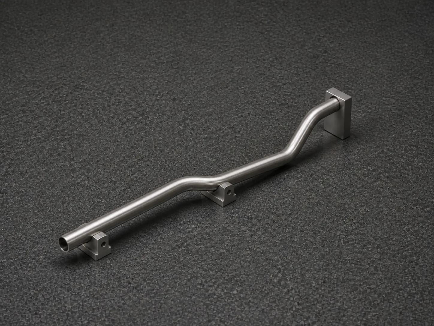
Illustrative two-bend stainless tube in a modular inspection fixture showing a primary bend and straight tangent legs, one open end with visible wall, and a raised terminal leg in a rotated second bend plane

Tube definition in one fixed inspection view

The open section, primary bend and tangencies, and raised terminal leg remain visible together while the request details change.

Illustrative example only; markers show request-review zones. They do not establish dimensions, material condition, bend or section conformance, end location, inspection acceptance, process route, equipment fit, or capability.

CNC tube-bending review

What should the tube and bend definition explain?

Select a review feature to see the details that help clarify the request.

Centerline radius, bend angle, tangencies, and straight lengths

Define each centerline radius, bend angle, tangent point, straight length, distance between bends, and the drawing or model convention used to locate the finished tube centerline.

  • Centerline radius and bend angle for every bend, with tangent locations and the convention used to dimension them
  • Straight lengths, distances between bends, bend sequence, and any stated clamp, support, or feature-clearance zones
  • Finished centerline, Cartesian, or model definition and the drawing datums that locate the requested geometry

Helpful tube-bending detail

For every bend, label the centerline radius, angle, tangent points, straight length, distance to the next bend, and the coordinate convention used by the drawing or model.

Start with your tube files
Process and tooling fit, achievable geometry and deformation limits, material condition, inspection method, fulfillment path, availability, and timing are confirmed from the submitted information during quote review.

Capabilities

Common CNC tube bending request patterns, kept easy to scan.

These examples organize the starting point. Process and tooling fit, achievable geometry and deformation limits, material and supplied-stock conditions, feature sequence, inspection scope, requested records, fulfillment, and timing are confirmed from the project files.

Single-bend, return-bend, and repeated-radius geometry

Routing geometry

Requests reviewed from the finished centerline path, each CLR and bend angle, tangent points, straight and end lengths, bend-allowance or developed-length convention when provided, cut and trim basis, bend direction and handedness, permitted springback-compensation basis, deformation limits, surface requirements, and inspection datums.

Multi-bend parts with controlled rotation and end clocking

Multi-plane

Requests reviewed from one unambiguous XYZ or LRA/YBC definition, start end, feed or length convention, rotation sign, plane-of-bend reference, bend order, distance between bends, handedness, terminal-leg and end clocking, collision-sensitive geometry, mating interfaces, and finished-path acceptance.

Round, square, rectangular, and other hollow profiles

Profiles

Profile requests reviewed from actual tube dimensions or nominal pipe size and schedule, wall and corner radii where applicable, easy-way or hard-way bend orientation when relevant, material specification and condition, welded or seamless construction, weld-seam position, grain or extrusion direction when controlled, finish, marking limits, and allowable cross-section change.

End features, attachments, and assembly fit-up

Interfaces

Requests reviewed from end cuts and trim stock, flares or other end forms when specified, holes, slots, notches, copes, bosses, brackets and fittings, feature-to-tangent spacing, before-or-after-bend intent, interface datums, insertion depth, end orientation, weld or attachment definition, finishing sequence, protected surfaces, and fit-up or inspection method.

Quote workflow

From controlled tube definition to a confirmed bending path.

A short, human-managed review keeps starting stock, bend coordinates, planes, ends, deformation limits, interfaces, inspection, and open questions visible before work is accepted.

  1. 01

    Share the controlled tube definition

    Upload the finished model and drawing, bend table or coordinate data, starting tube or pipe specification, profile and wall, material and condition, seam requirement, bend radii and angles, tangencies and straight lengths, rotations and planes, end features and interfaces, deformation and surface limits, inspection definition, quantity, and target timing.

  2. 02

    Reconcile bend, section, and interface drivers

    The tube-versus-pipe size convention, profile and wall, material condition, seam position, CLR and angle, tangencies, straight and end lengths, coordinate convention, rotation and bend-plane references, bend order, end clocking, nearby features, mating datums, deformation limits, surface requirements, and inspection state are organized for follow-up.

  3. 03

    Confirm the project path

    Process and tooling fit, achievable bend geometry and deformation limits, material and supplied-stock conditions, feature sequence, inspection method and scope, requested record fields, fulfillment, timing, and remaining questions are resolved before acceptance.

  4. 04

    Coordinate the approved baseline

    Once a request is accepted, the controlled drawing and model revision, starting-stock definition, bend data and coordinate convention, end and interface requirements, deformation and surface limits, inspection state, acceptance criteria, requested record boundary, quantity, timing, and authorized changes become the reference point for project communication.

Request readiness

Small decisions that make CNC tube bending requests easier to review.

Clear starting-stock, bend-path, plane, end, deformation, and inspection intent is more useful than a generic bend note or an assumed process result.

Design intent before assumptions
  1. 01

    Distinguish tube outside dimensions from nominal pipe size.

    State whether the starting product is tube identified by actual outside dimensions and wall or pipe identified by nominal size and schedule. Add profile dimensions and corner radii for square, rectangular or shaped sections, plus the governing material specification, grade, condition, welded or seamless construction, and supplied-stock source.

  2. 02

    Use one centerline and coordinate convention.

    Provide a finished centerline model plus a drawing or bend table that defines origin, axes, units, start end, bend direction, rotation sign, and whether dimensions are XYZ, length-rotation-angle (LRA/YBC), tangent-to-tangent, bend-center, intersection-point, or another stated convention.

  3. 03

    Show every CLR, angle, tangent, straight, and trim boundary.

    Identify centerline radius rather than leaving inside or outside radius ambiguous, mark both tangent points, distinguish distance between bends from center-to-center distance, define straight and end lengths, developed-length or bend-allowance basis when controlled, and any trim stock or cut-after-bend intent.

  4. 04

    Make rotations, planes, handedness, and ends unambiguous.

    Name the start and finish ends, show bend order and direction, define plane of bend and rotation between bends, mark handed variants, set the clock reference for terminal legs and end features, and identify end-face orientation and mating-interface datums.

  5. 05

    Treat material condition, seam orientation, and surface contact as requirements when they matter.

    Specify alloy or grade, temper, heat-treatment or hardness condition when applicable, welded or seamless form, allowed seam location through each bend, lot-consistency need, pre-existing finish, protected or cosmetic zones, permissible tooling and grip marks, and prohibited scratches or contamination.

  6. 06

    Define the finished shape and deformation acceptance together.

    State centerline or profile, angle, radius, distance-between-bends, end-position and end-orientation requirements alongside the ovality or flattening calculation, wall-thinning or minimum-wall basis, allowable wrinkles, kinks, collapse and cracking, free or restrained inspection state, datum and fixture scheme, measurement method, coverage, and requested records.

Materials

Common tube-material request contexts for bending review.

Material identity is one layer of the request. Exact specification, grade, temper or condition, tube form, dimensions, wall, seam, finish, bend geometry, deformation limits, supplied-stock context, inspection, and availability are confirmed for each project.

Material guide

Stainless steel

Stainless tube requests where exact alloy and annealed or cold-worked condition, welded or seamless construction, outside dimensions and wall, weld-seam orientation, CLR and multi-plane geometry, surface-protection and marking limits, springback basis, ovality and wall-thinning limits, end features, cleaning or finish condition, and inspection method need review.

304/304L · 316/316L examples

View material
Material guide

Aluminum

Aluminum tube and extrusion requests where alloy and temper, round or shaped profile, outside dimensions, wall and corner radii, extrusion seam or grain direction when controlled, bend orientation, CLR and angles, straight lengths, surface marking, flattening or cracking limits, springback basis, end geometry, and inspection state need review.

5052 · 6061 · 6063 examples

View material
Material guide

Copper

Copper tube requests where alloy, temper, actual outside dimension and wall or product designation, starting hardness and finish, bend radius and angle, straight and end lengths, multi-plane rotation, surface-protection and cleanliness requirements, flattening, wrinkling and wall-thinning limits, fitting interfaces, and inspection method need review.

C10200 · C11000 · C12200 examples

View material
Material guide

Brass

Brass tube and hollow-profile requests where exact alloy and temper, outside dimensions and wall, seam and surface condition, bend orientation and CLR, feature and end relationships, cosmetic or contact-surface limits, cracking, wrinkling, flattening and wall-thinning acceptance, mating interfaces, and inspection state need review.

C26000 · C27000 · C33000 examples

View material

FAQ

CNC tube bending quote questions.

Start with a private STEP or STP model and matching PDF drawing, a bend table when available, or a written project description. Identify tube or pipe size convention, profile and wall, material specification and condition, seam requirement, every CLR and bend angle, tangencies and straight lengths, rotations and bend planes, start and finish ends, end features and interfaces, deformation and surface limits, inspection definition, quantity, and timing. Tube bending is not a dedicated Process option in the current form, so leave it unset or select Other when useful and name CNC tube bending in the description.

Centerline radius, or CLR, is measured from the bend center to the tube centerline. It differs from inside and outside bend radius, so the drawing should name the intended radius convention. Pair each CLR with its angle, tangent points, straight and end lengths, profile orientation, and any bend-to-bend relationship so the geometry and tooling review starts from one definition.

Starting profile and dimensions, wall, material specification and condition, welded or seamless construction, seam position, CLR relative to section size, outside-dimension-to-wall relationship, bend angle, straight grip and tangent lengths, bend spacing and sequence, rotation between bends, end geometry, nearby features, surface-marking limits, allowable ovality, flattening, wall thinning, wrinkling and cracking, quantity, and inspection method all matter. The accepted route is confirmed from the complete request rather than a generic radius rule.

Use a controlled three-dimensional model plus one stated coordinate convention. XYZ can locate centerline points in a defined datum frame; LRA/YBC can define each feed or length, rotation, and bend angle. Name the start end, origin, axes, units, bend direction and order, rotation sign, plane-of-bend reference, tangent or bend-center convention, handedness, terminal-leg clocking, and end-feature orientation so two reviewers interpret the same path.

Inspection and documentation requirements can be reviewed during quoting. No certification or report package is implied until confirmed.

Include every requested adjacent operation in the drawing and description, including cut and trim basis, end forms, holes, slots, notches, copes, brackets, fittings, welds, surface preparation, coating, masking, hardware, assembly interfaces, sequence, inspection, and packaging. Process compatibility, sequence, combined scope, availability, and the accepted route are confirmed during review. Requests are reviewed manually. The fulfillment route and availability are confirmed before acceptance.

Start with the files you have

Ready to review your CNC tube bending request?

Share the finished tube model and drawing, bend table or coordinate data, starting tube or pipe definition, profile and wall, material and condition, seam requirement, CLR and bend angles, tangencies and straight lengths, rotations and bend planes, end features and interfaces, deformation and surface limits, inspection and record requirements, quantity, and timing. Pearson will follow up on the details that still need confirmation.

Request a tube-bending quote