Feature-led review
Pockets, profiles, slots, holes, threads, inside radii, and edge requirements are organized before the process path is confirmed.
CNC milling services
Pockets, inside radii, hole patterns, datum faces, and edge requirements all shape the manufacturing plan. Share the model and drawing so Pearson can review what is functional and confirm the project path before acceptance.
Capability review
This page describes common request types. Available processes, equipment, tolerances, inspection, documentation, and fulfillment are confirmed for each quote.
Overview
A useful milling review starts with the part function, the geometry that drives cutter access, and a drawing that identifies the faces, holes, fits, and finishes that are actually critical.
Pockets, profiles, slots, holes, threads, inside radii, and edge requirements are organized before the process path is confirmed.
Part orientation, workholding surfaces, feature depth, and relationships across faces help reveal likely setup questions early.
Datums, mating faces, fits, finish areas, and inspection expectations belong in the request instead of being inferred later.
Fulfillment review
Requests are reviewed manually. The fulfillment route and availability are confirmed before acceptance.
Quote inputs
You do not need every answer before submitting. Share what is known and mark the rest for follow-up.
Interactive milling review
Select a feature on the sample fixture plate to see what the model and drawing should communicate before the project path is confirmed.
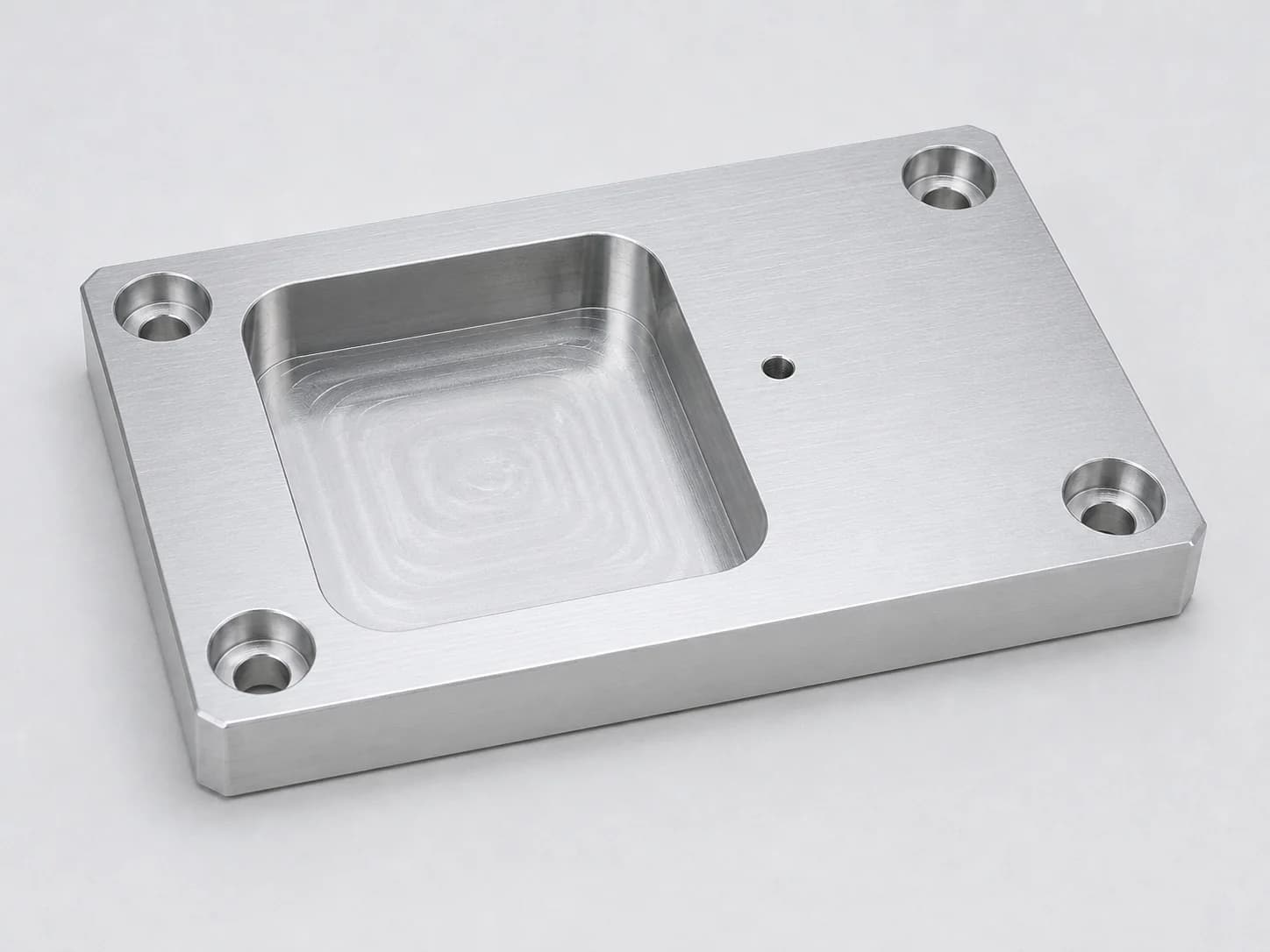
Sample fixture plate feature map
The numbered markers match the labels below and the review panel.
Illustrative example only; markers identify features, not dimensions or tolerances.
Milling feature explorer
Choose a feature to see the details that help Pearson understand the request.
Pocket depth, wall geometry, and the smallest inside radius influence tool selection, reach, and the likely cutting approach.
Helpful upload
Use the 3D model for geometry and mark critical pocket dimensions, radii, and floor requirements on the drawing.
Illustrative part only. Geometry, equipment fit, tolerances, inspection, and documentation are confirmed from your files during quote review.
Capabilities
These examples help identify the likely starting point. Exact equipment fit, achievable tolerances, and availability are confirmed from the project files.
Plates, brackets, housings, covers, adapters, pockets, slots, profiles, and fixture components with features on flat or stepped faces.
Clearance holes, dowel locations, counterbores, countersinks, tapped features, and hole patterns defined by function.
Geometry that crosses faces or depends on a shared datum may require additional orientation, access, and inspection review.
Edge condition, surface treatment, critical dimensions, documentation, and inspection intent reviewed with the part request.
Quote workflow
A short, human-managed review keeps geometry and open questions visible before work is accepted.
Upload the model, drawing, photos, quantity, material preference, and known functional requirements.
Pockets, radii, access, hole details, datums, finish, and inspection intent are organized for follow-up.
Equipment fit, tolerances, fulfillment, timing, and remaining questions are resolved before acceptance.
Approved drawings and requirements become the reference point for production communication and delivery planning.
Drawing readiness
Clear functional intent is more useful than applying tight requirements everywhere.
Round milling cutters leave an internal radius. More generous corners can improve access and reduce reliance on smaller tools.
Depth relative to width can affect cutter reach, rigidity, chip removal, and the number of passes needed.
Apply close requirements to the fits, faces, bores, and locations that affect how the part works.
Include diameter, depth, counterbore, thread, fit, and pattern intent where those details matter.
Show how mating faces and features across setups relate instead of leaving the inspection origin unclear.
Separate functional, cosmetic, deburred, chamfered, and surface-treated areas on the drawing.
Materials
Grade, form, condition, finish, and availability are confirmed for each request.
Brackets, housings, plates, fixtures, prototypes, and lightweight prismatic parts.
6061-T6 · 7075-T6 · MIC-6 examples
View materialMachine components, tooling details, brackets, fixture elements, and wear-related applications.
1018 · 1045 · 4140 · tool steel examples
View materialCorrosion-resistant plates, brackets, housings, and equipment components.
303 · 304 · 316/316L examples
View materialGuides, spacers, nests, fixtures, wear parts, and other non-metallic details.
Acetal · UHMW · Nylon · ABS · PC examples
View materialContinue exploring
Review the broader machining service guide.
Explore cylindrical parts and turned-feature requests.
Review hole-making and threading requests.
Explore one-off, repair, rework, and toolroom milling requests.
See common machinery, fixture, and equipment applications.
See common bracket, mounting, fixture, and automation applications.
FAQ
A STEP or STP model and a PDF drawing are the best starting pair. Add quantity, material preference, pocket and hole details, datum intent, finish, inspection or documentation needs, and target timing when known.
Plates, brackets, housings, fixture plates, covers, adapters, blocks, pockets, slots, profiles, hole patterns, and features across multiple faces can be submitted for review.
Show the pocket geometry in the model and identify critical depth, floor, wall, and inside-radius requirements on the drawing. Round cutters leave an internal radius, so the smallest functional corner should be clear.
Identify the dimensions, fits, faces, and relationships that affect function. Achievable tolerances and the required inspection approach are confirmed from the drawing during quote review.
Include the required finish, affected surfaces, critical dimensions, and documentation expectations in the request. Scope and availability are confirmed before acceptance.
Requests are reviewed manually. The fulfillment route and availability are confirmed before acceptance.
Start with the files you have
Share the model, drawing, photos, and known requirements. Pearson will follow up on the details that still need confirmation.
Request a milling quote